
Device for measuring the firing rate of shots fired by a barrel of a weapon

a technology of firing rate and barrel, which is applied in the direction of instruments, heat measurement, weapons, etc., can solve the problems of difficult association, troublesome special connection of the barrel, and inability to measure the firing rate of shots, so as to improve the maintenance and calculation of the effective firing rate of shots. , the effect of ensuring the safety of the weapon

Inactive Publication Date: 2019-12-26
FN HERSTAL
View PDF0 Cites 19 Cited by
  • Summary
  • Abstract
  • Description
  • Claims
  • Application Information

AI Technical Summary

Benefits of technology

The invention is a device that can be attached to a gun and continuously monitor its activity without needing an external power source. This device helps to calculate the effective rate of fire of the gun, which can help improve maintenance and safety. It measures the heating of the gun barrel and assesses the state of wear by measuring the rate at which shots are fired.

Problems solved by technology

Measuring the number of shots fired and the associated intervening time periods from the frame of the weapon does not make it possible, except through association with the barrel ID, to determine to what a given barrel has already been subjected.
Such an association is not easy to carry out.
Specifically, the procedure for replacing the barrel and the environmental conditions, which are often difficult, render it troublesome to make a special connection between the barrel and the body of the machine gun.
Moreover, for the user to identify the barrel in the counter system, in particular in a stressful situation, is too much to ask.
Specifically, despite power cells being able to achieve service lives of several tens of years, their aging is difficult to predict.
However, measuring the effective rate of fire using a batteryless device is troublesome, given that it is necessary to have enough energy between two successive shots to supply the measurement device with power.
The times between two events are long and unpredictable.
This is not straightforward, especially considering the substantial environmental constraints specific to (both military and civil) gunsmithing.
Since the barrel can be detached from the rest of the weapon, it will be difficult to enable the shot counter located on the body of the weapon to communicate reliably and ergonomically, wirelessly or otherwise, with a system for measuring the effective rate of fire located at the barrel.
The energy recovery devices used for shot counting are generally unsuitable for measuring the effective rate of fire.

Method used


Image

  • Device for measuring the firing rate of shots fired by a barrel of a weapon
  • Device for measuring the firing rate of shots fired by a barrel of a weapon
  • Device for measuring the firing rate of shots fired by a barrel of a weapon

Examples


Embodiment Construction

[0043]The device according to the invention measures the effective rate of fire from a barrel of a weapon. This device can be adapted for any type of barrel for any type of automatic, semi-automatic or manually loaded firearm (rifle, pistol, machine gun, submachine gun, etc.).

[0044]To estimate the aging of the barrel by measuring the effective rate of fire, the temperature history of the barrel is analyzed. The device of the invention is self-powered by means of a thermoelectric generator using the heating of the barrel as an energy source, thereby avoiding the drawbacks related to the use of a power cell.

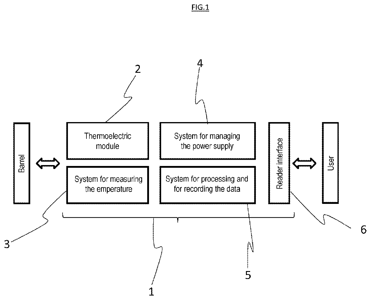
[0045]The device 1, as shown in FIG. 1, comprises a thermoelectric generator 2 that is capable of recovering the heat from firing to generate electricity and to supply power to all of the other components included in the device 1 that consume energy.

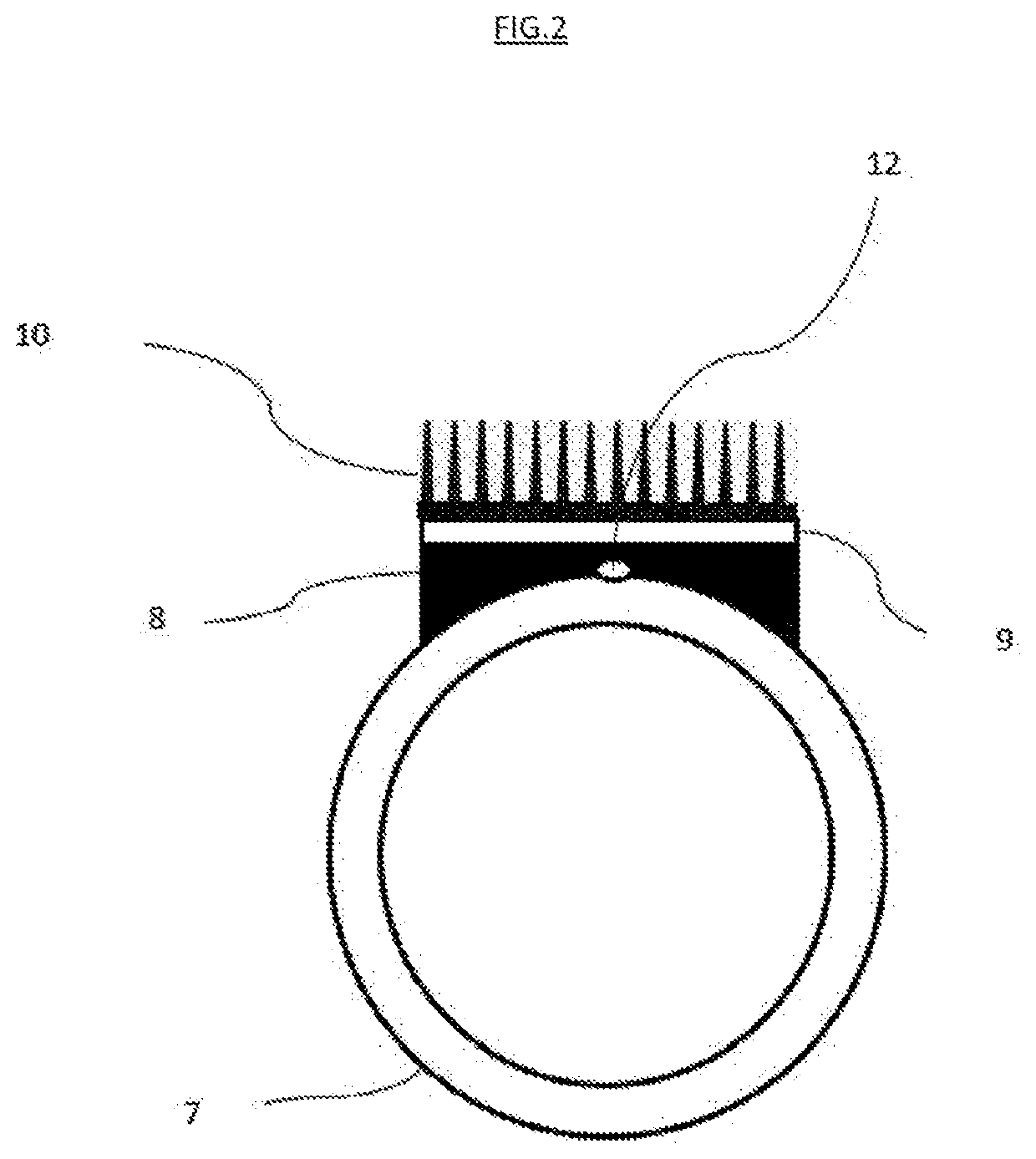
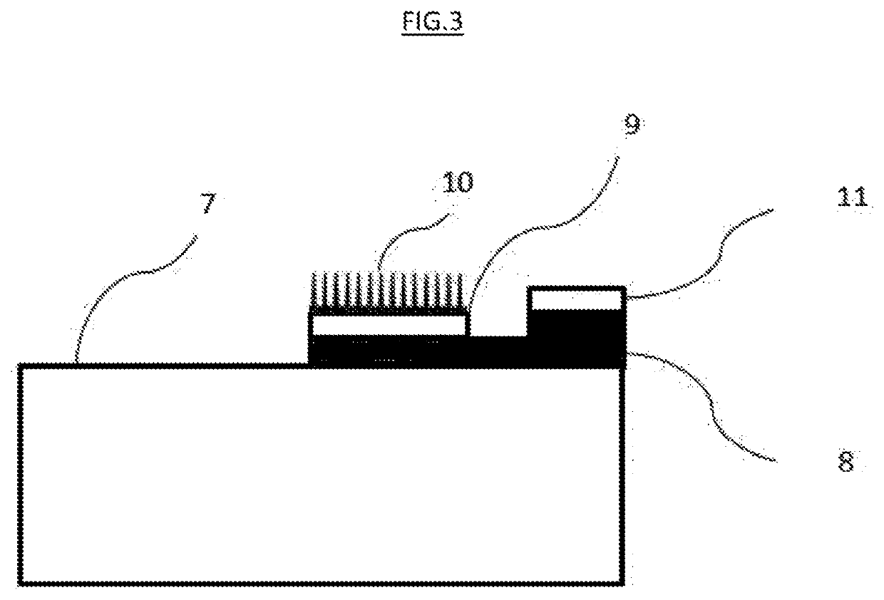
[0046]Additionally, the device 1 comprises a system 3 for calculating / measuring the temperature of the barrel 7, this system being sup...


PUM

PropertyMeasurementUnit
temperatureaaaaaaaaaa
thermal energyaaaaaaaaaa
temperatureaaaaaaaaaa

Abstract

The present invention relates to a self-powered device for measuring a firing rate, comprising: a) a thermoelectric generator (2) that converts thermal energy into electrical energy; b) a system (3) that is able to determine the temperature of the barrel (7); c) a system for processing and recording said measurements (4); d) characterized in that the system for determining temperature (3) and the system for processing and recording measurements (4) are powered by the thermoelectric generator (2).

Description

SUBJECT OF THE INVENTION[0001]The present invention relates to a self-powered device for measuring the effective rate of fire of shots fired from the barrel of a weapon.[0002]The present invention also relates to any type of barrel including this device.[0003]The present invention further relates to a method for measuring the effective rates of fire of a weapon.PRIOR ART[0004]The wear on a weapon and hence the maintenance to be performed depends in particular on the effective rate of fire. The effective rate of fire is the number of shots fired by the user over a given time period. Consequently, the effective rate of fire is representative of how intensively the weapon is used and, as such, of barrel heating. This heating is itself representative of the wear caused on the weapon and on the barrel.[0005]Currently, effective rates of fire are measured by devices that are located in the frame of the weapon, and are not connected to the barrel. However, it would be advantageous to have ...

Claims


Application Information

Patent Timeline
Patent Type & Authority Applications(United States)
IPC IPC(8): F41A19/01F41A21/00F41A13/12G01K1/14
CPCF41A19/01F41A13/12G01K1/143F41A21/00F41A13/00F41A21/32H10N10/17H10N10/13
Inventor LIBOTTE, HUGUES
Owner FN HERSTAL
Learn More