Eureka AIR delivers breakthrough ideas for toughest innovation challenges, trusted by R&D personnel around the world.

Gas-phase chemical reactor and method of using same

Active Publication Date: 2019-12-12
ASM IP HLDG BV
View PDF4 Cites 176 Cited by
  • Summary
  • Abstract
  • Description
  • Claims
  • Application Information

AI Technical Summary

Benefits of technology

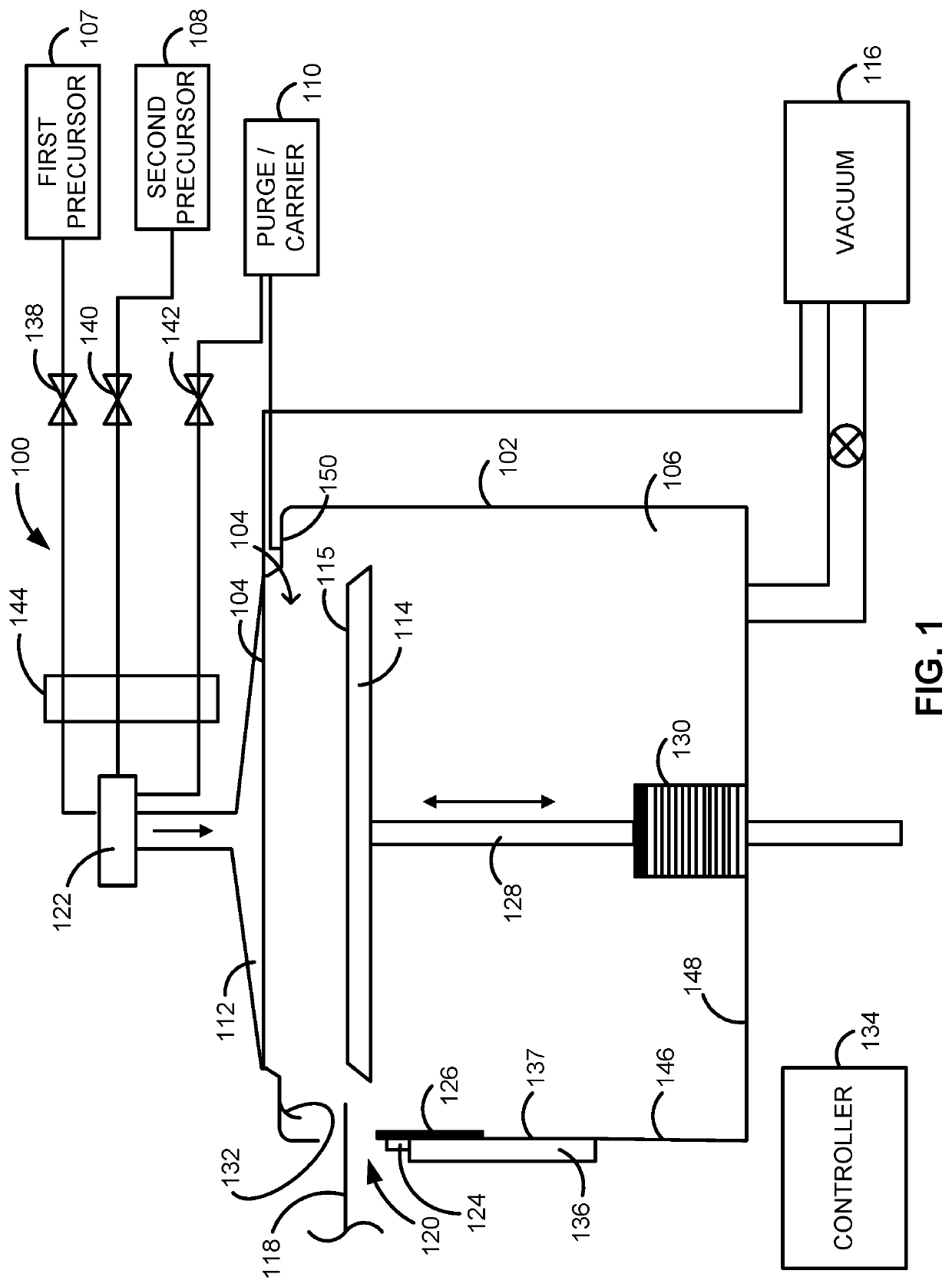
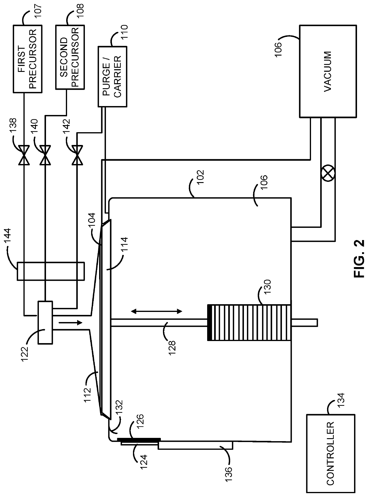
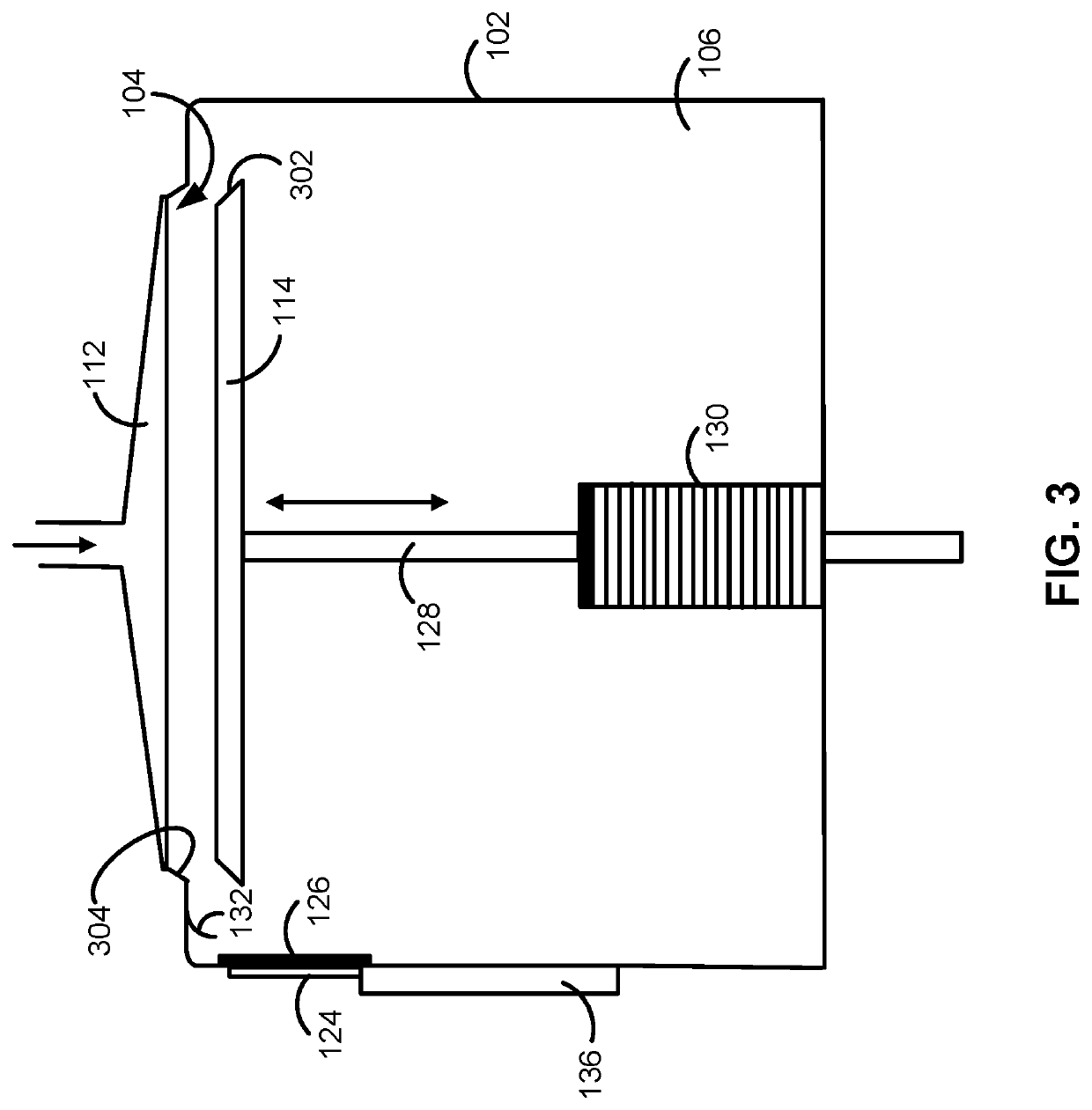
The present invention provides an apparatus and method for a gas-phase chemical reactor that allows extended residue time, partial pressure, and / or absolute pressure of precursors. This system can reduce the usage of precursors and waste, resulting in lower costs for processing substrates. It can also facilitate high growth rates and drive reactions that might not occur without the invention. Additionally, this invention allows for rapid purging / evacuation of gas from the reaction region and does not require expensive gas distribution apparatus for process uniformity.

Problems solved by technology

While such technique works relatively well for some applications, for other applications, continuously flowing one or more precursors during substrate processing can result in undesired waste of unreacted precursors, undesirably long substrate process times, and / or films with undesirable properties.
Further, using such techniques, it may be difficult to obtain desired concentrations, partial pressures and / or absolute reaction chamber pressures desired to drive some reactions.
Such high partial pressures can be difficult to achieve with typical reactors.
Additionally, formation of self-assembled monolayers can require relatively long exposure times and / or relatively high precursor concentrations / partial pressures to achieve desired film properties, and such conditions can be difficult to obtain with typical reactors.
Furthermore, chemical gas-phase reactors often employ relatively expensive gas-distribution apparatus to uniformly distribute gas across a substrate surface; such designs may be desired when the precursor(s) continuously flow across a substrate surface.

Method used


Image

  • Gas-phase chemical reactor and method of using same
  • Gas-phase chemical reactor and method of using same
  • Gas-phase chemical reactor and method of using same

Examples


Embodiment Construction

[0021]The description of exemplary embodiments of reactors, systems, and methods provided below is merely exemplary and is intended for purposes of illustration only; the following description is not intended to limit the scope of the disclosure or the claims. Moreover, recitation of multiple embodiments having stated features is not intended to exclude other embodiments having additional features or other embodiments incorporating different combinations of the stated features.

[0022]Any ranges indicated in this disclosure may include or exclude the endpoints. Additionally, any values of variables indicated (regardless of whether they are indicated with “about” or not) may refer to precise values or approximate values and include equivalents, and may refer to average, median, representative, majority, or the like.

[0023]As used herein, precursor references to one or more gasses that take part in a chemical reaction. The chemical reaction can take place in the gas phase and / or between ...


PUM

PropertyMeasurementUnit
Pressureaaaaaaaaaa
Flow rateaaaaaaaaaa
Volumeaaaaaaaaaa

Abstract

A gas-phase chemical reactor, a system including the reactor, and methods of using the reactor and system are disclosed. An exemplary reactor includes a reaction chamber and is configured to provide a precursor within the reaction chamber for a soak period—e.g., a period wherein a supply of the precursor to the reaction chamber is ceased and before purging of the reaction chamber begins. This allows relatively high residence times, relatively high partial pressures of the precursor(s) and / or a relatively high absolute pressure to be obtained within the reaction chamber during substrate processing.

Description

FIELD OF INVENTION[0001]The disclosure generally relates to gas-phase apparatus and processes. More particularly, exemplary embodiments of the present disclosure relate to gas-phase chemical reactors suitable for precursor soak applications, systems including such reactors, and to methods of using the reactors and systems.BACKGROUND OF THE DISCLOSURE[0002]Gas-phase chemical reactors can be used for a variety of applications, such as for depositing and / or etching material on a surface of a substrate. A typical gas-phase chemical reactor includes a reaction chamber, a gate-valve that opens to receive a substrate and closes during substrate processing, and one or more gas sources coupled to the reaction chamber.[0003]During substrate processing, one or more precursors flow into the reaction chamber to deposit material onto a substrate surface and / or to react with material on the substrate surface to etch the material. Generally, during substrate processing, the flow of the gas(es) reac...

Claims


Application Information

Patent Timeline
IPC IPC(8): C23C16/455H01J37/32C23C16/52C23C16/54
CPCH01J37/32743H01J37/32788H01J37/32477H01J37/32449C23C16/54C23C16/45536C23C16/45544C23C16/52H01J2237/332C23C16/458C23C16/455C23C16/4401C23C16/4412C23C16/45561C23C16/4581C23C16/45502C23C16/45527C23C16/4404C23C16/4583H01J37/3244C23C16/45565C23C16/50
Inventor NISKANEN, ANTTI JUHANI
Owner ASM IP HLDG BV
Why Eureka
Eureka Blog
Learn More