
Method and apparatus for providing automatic mirror setting via inward facing cameras

a technology of automatic mirror setting and inward facing camera, applied in the field of communication networks, can solve the problems of driver often times having a large or big blind spot, model training generally requires intensive computation, and the driver often times has a large or large blind spo

Inactive Publication Date: 2019-12-05
XEVO INC
View PDF0 Cites 6 Cited by
  • Summary
  • Abstract
  • Description
  • Claims
  • Application Information

AI Technical Summary

Benefits of technology

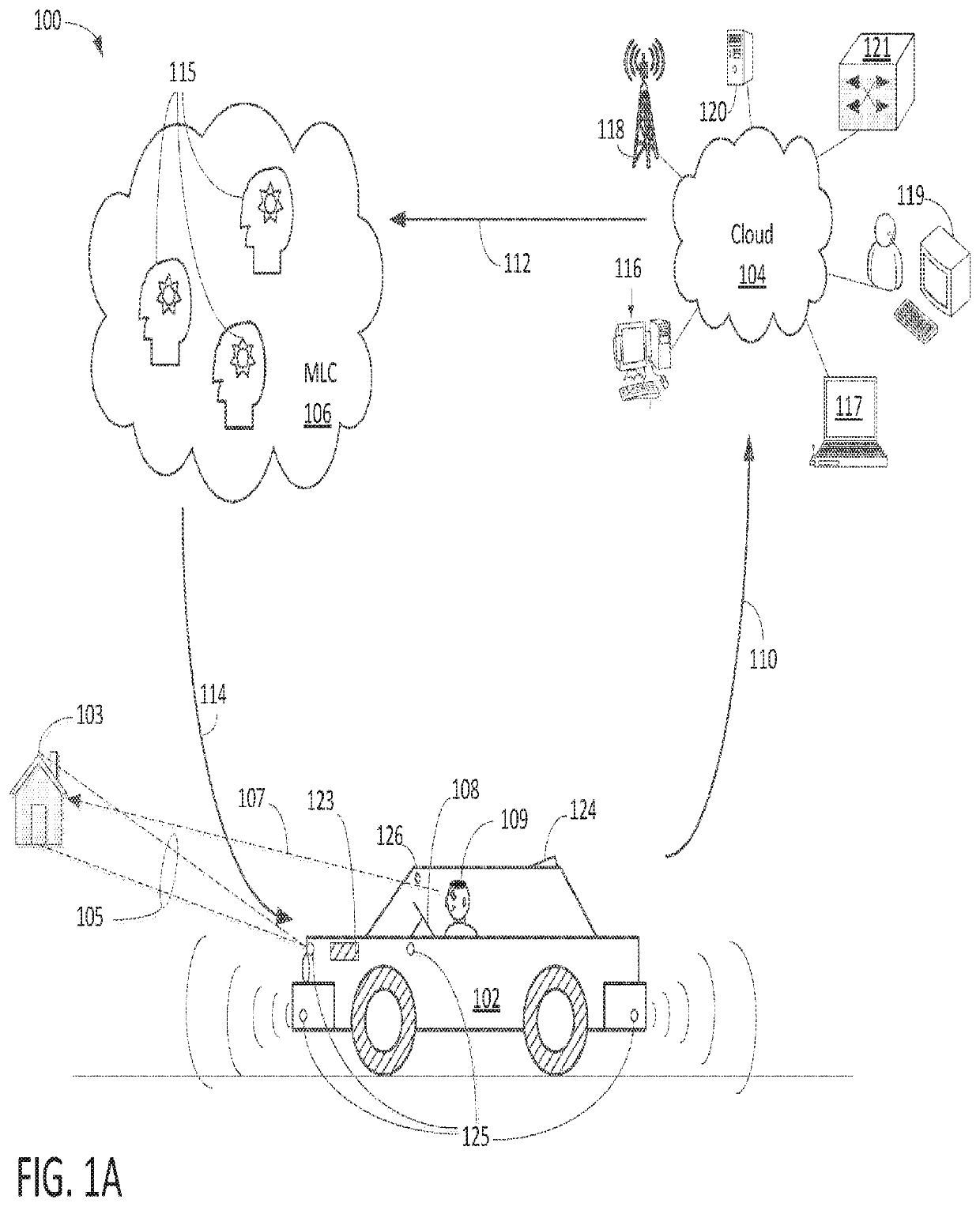
The patent describes an adaptive mirror system for vehicles that can adjust its orientation to minimize blind spots and track abnormal events in the external environment. The system uses an AM model that dynamically adjusts the orientation of mirrors based on external images and real-time data from a cloud-based system. The AM model is trained by a MLC that uses labeled data from a CBN to improve its performance. The system can also use one of the external mirrors to track an abnormal event and provide a notice to the driver. The labeled data from the driver's reaction to the abnormal event is used to update the AM model at the MLC. Overall, the system improves safety and driver awareness by reducing blind spots and enhancing situational awareness.

Problems solved by technology

Model training generally requires intensive computation.
As such, real-time response via machine learning model can be challenging.
A drawback associated with a traditional automobile or vehicle is that most mirrors, especially external mirrors, on both sides of the vehicle are typically set incorrectly so the driver often times has a large or big blind spot on both sides of the vehicle.

Method used


Image

  • Method and apparatus for providing automatic mirror setting via inward facing cameras
  • Method and apparatus for providing automatic mirror setting via inward facing cameras
  • Method and apparatus for providing automatic mirror setting via inward facing cameras

Examples


Embodiment Construction

[0027]Embodiments of the present invention are described herein with context of a method and / or apparatus for facilitating automatic mirror adjustment based on images captured by inward facing cameras via an AM model continuously trained by a virtuous cycle containing a cloud based network, a containerized sensing device, and a machine learning center (“MLC”).

[0028]The purpose of the following detailed description is to provide an understanding of one or more embodiments of the present invention. Those of ordinary skills in the art will realize that the following detailed description is illustrative only and is not intended to be in any way limiting. Other embodiments will readily suggest themselves to such skilled persons having the benefit of this disclosure and / or description.

[0029]In the interest of clarity, not all of the routine features of the implementations described herein are shown and described. It will, of course, be understood that in the development of any such actual...


PUM


Abstract

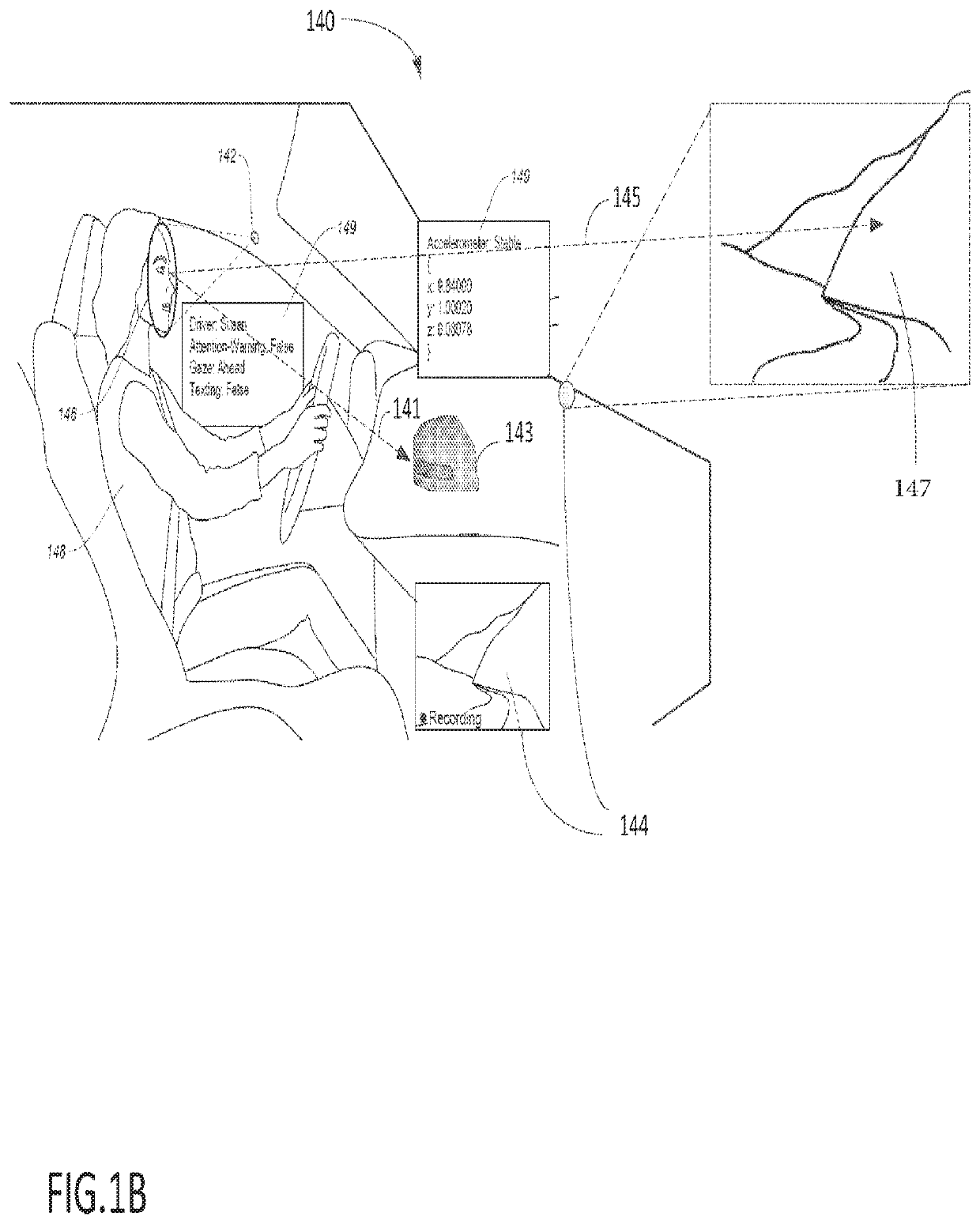
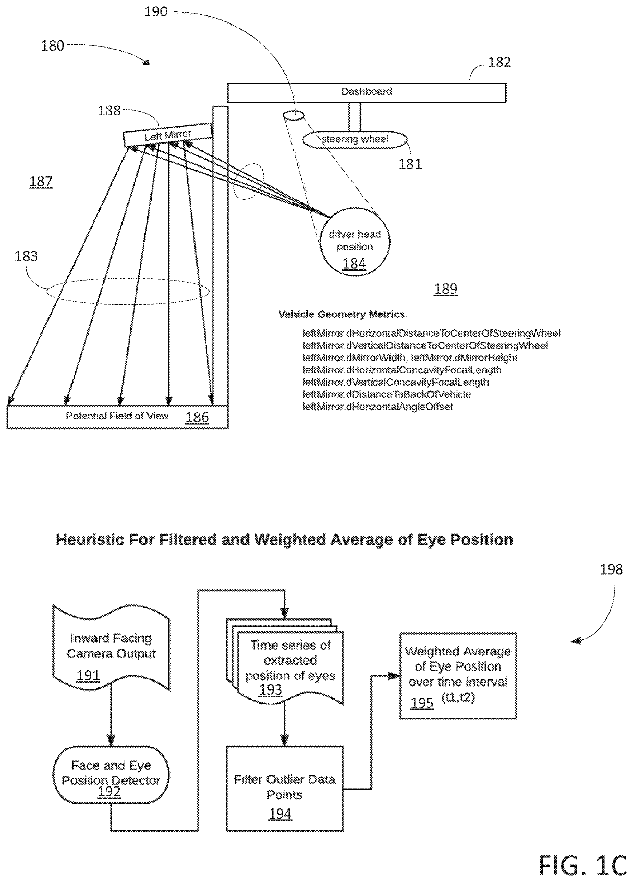
A method or system that is able to adjust an exterior mirror of a vehicle via an automatic mirror-setting (“AM”) model managed by a virtuous cycle containing a cloud based network (“CBN”). The system includes a set of mirrors, a set of inward facing cameras, a vehicle onboard computer (“VOC”), and AM module. In one embodiment, the mirrors, attached to a vehicle, are configured to capture at least a portion of the external environment in which the vehicle operates. The inward facing cameras, mounted in the vehicle, are configured to collect internal images, including the operator's facial features showing operator visual characteristics. The VOC, which is coupled to the CBN, is configured to determine operator vision metadata based on the internal images, operator visual characteristics, and historical stored data. The AM module is able to adaptively set a mirror to an optimal orientation so that the area of the external blind spot is minimized.

Description

BACKGROUNDTechnical Field[0001]The exemplary embodiment(s) of the present invention relates to the field of communication networks. More specifically, the exemplary embodiment(s) of the present invention relates to operating an intelligent machine using a virtuous cycle between cloud, machine learning, and containerized sensors.Description of the Related Art[0002]With increasing popularity of automation and intelligent electronic devices, such as computerized machines, the Internet of Things (“IoT”), smart vehicles, smart phones, drones, mobile devices, airplanes, artificial intelligence (“AI”), the demand of intelligent machines and faster real-time response are increasing. To properly provide machine learning, a significant number of pieces, such as data management, model training, and data collection, needs to be improved.[0003]A conventional type of machine learning is, in itself, an exploratory process, which may involve trying different kinds of models, such as convolutional, ...

Claims


Application Information

Patent Timeline
Patent Type & Authority Applications(United States)
IPC IPC(8): G06K9/00B60Q9/00G06K9/66G08G1/16G08G1/01G08G1/04B60R1/00B60R1/04B60R1/062G01C21/36G01S19/48G08G1/0968G08G1/14H04N7/18G06N20/00
CPCG08G1/166G06K9/00845G08G1/0129G06K9/00281G08G1/04G08G1/0112B60R1/04G01S19/48B60Q9/008H04N7/188G06K9/00832G06N20/00G06K9/00798G05D1/0246G05D1/0214G01C21/3605G06K2209/27B60R2300/105G08G1/143B60R1/00G06K9/00805G06K9/66G06K9/00604G06K9/00791G06K9/00979G06K9/00812G08G1/096888B60R2300/8006B60R1/062G01C21/3602G08G1/0116G08G1/096811G08G1/096861G08G1/0969H04W4/02H04L67/10H04W4/44G06N3/08G06F3/013G01S19/485G06N3/045G08B21/06G06V20/597G06V10/95G06V20/56G06V20/58G06V20/59G06V20/586G06V20/588G06V40/19G06V40/171G06V2201/10
Inventor CORDELL, JOHN PALMERWELLAND, ROBERT VICTORMCKELVIE, SAMUEL JAMESLUDWIG, JOHN HAYES
Owner XEVO INC
Learn More