
Bi-directional optical sub assembly connecting structure

a connecting structure technology, applied in the direction of printed circuit manufacturing, printed circuit non-printed electric component association, printed circuit aspects, etc., can solve the problems of solder shorts during the soldering process, very difficult soldering, and risk of damage to the internal components of the bi-directional optical sub assembly, so as to achieve easy electrical connection

Inactive Publication Date: 2019-11-28
XAVI TECH
View PDF7 Cites 1 Cited by
  • Summary
  • Abstract
  • Description
  • Claims
  • Application Information

AI Technical Summary

Benefits of technology

[0005]It is a main object of the present invention to provide a bi-directional optical sub assembly connecting structure which can easily electrically connect a bi-directional optical sub assembly to a printed circuit board.

Problems solved by technology

Also, executing the soldering is very difficult.
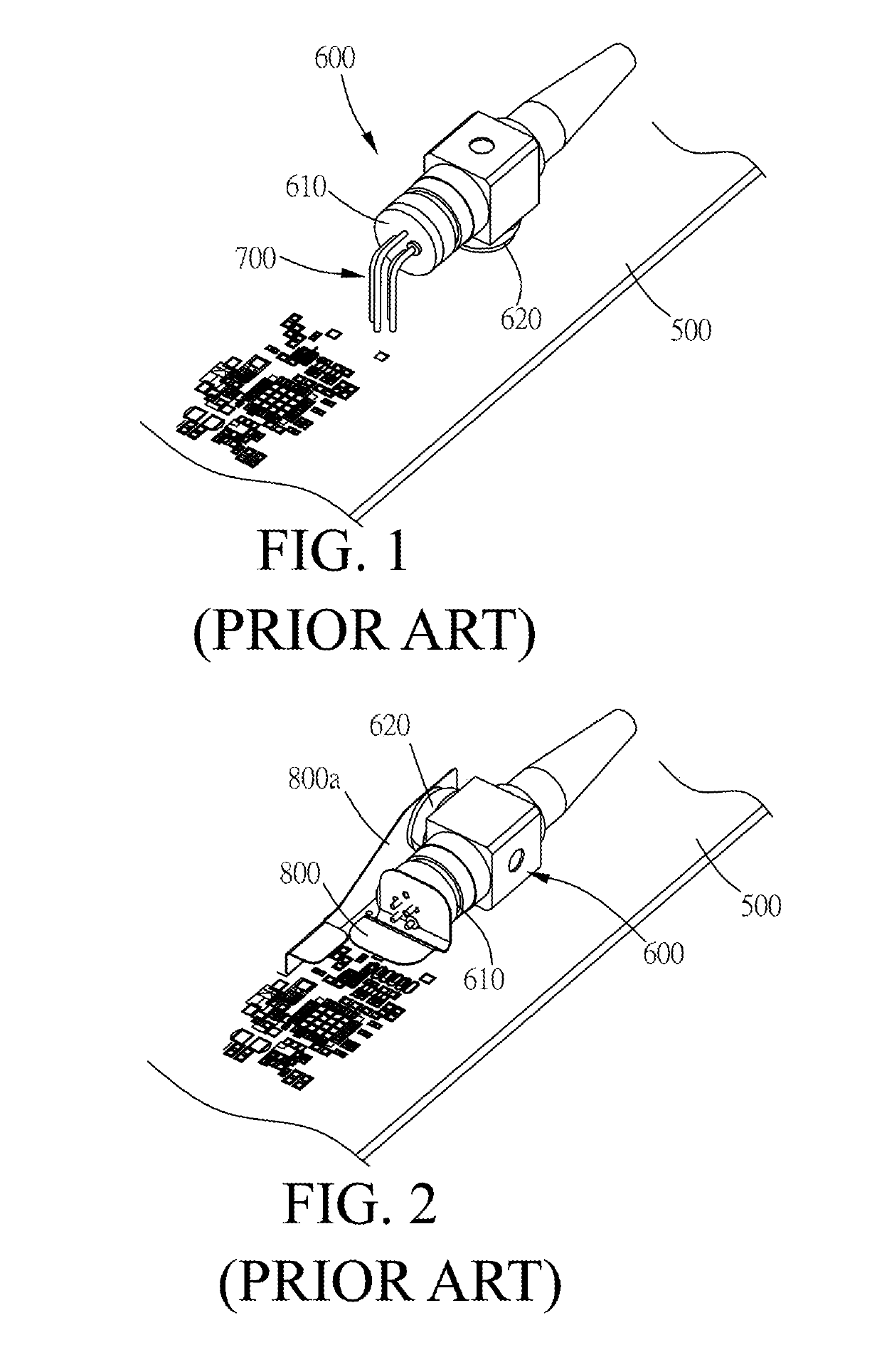
However, there is still a risk of damage to the internal components of the bi-directional optical sub assembly 600 even when the special bending jig is used in the forming process.
Moreover, the structure of the pins 700 and the bi-directional optical sub assembly 600 is likely to form solder bridges, which cause solder shorts during the soldering process.
Furthermore, according to practical experiments, the pins 700 cause interference with the transmission of signals, so they are not suitable for the high-speed communication specification of at least 10 Gbit / s.
In addition, when the bi-directional optical sub assembly 600 transmits electronic signals, it causes electromagnetic interference.
However, the degree of difficulty in soldering the connecting plates 800 and 800a to the printed circuit board 500 is still high.
In addition, when the bi-directional optical sub assembly 600 as shown in FIG. 2 transmits electronic signals, it causes electromagnetic interference.

Method used


Image

  • Bi-directional optical sub assembly connecting structure
  • Bi-directional optical sub assembly connecting structure
  • Bi-directional optical sub assembly connecting structure

Examples


Embodiment Construction

[0023]The advantages and innovative features of the invention will become more apparent from the following detailed description when taken in conjunction with the accompanying drawings.

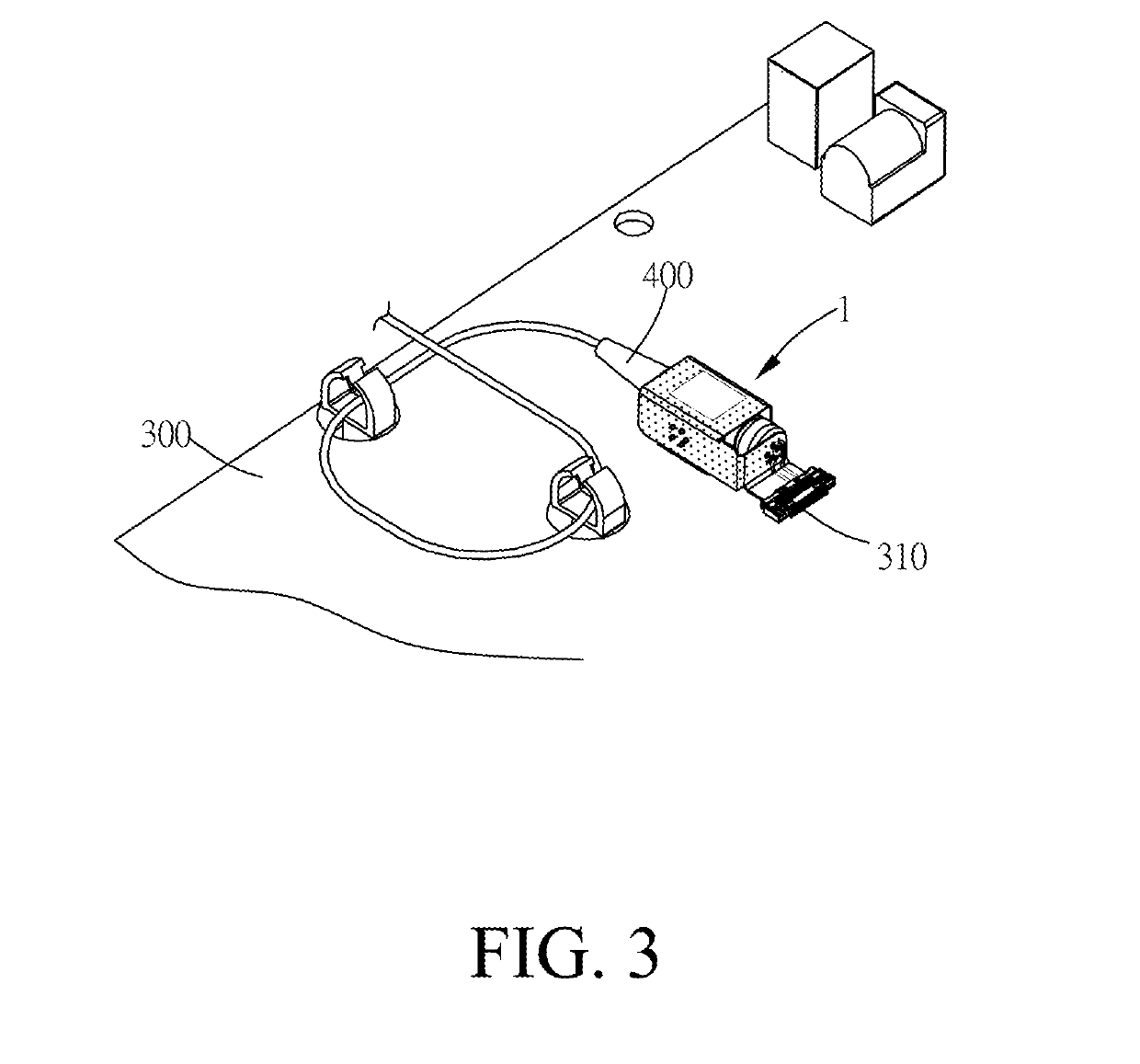
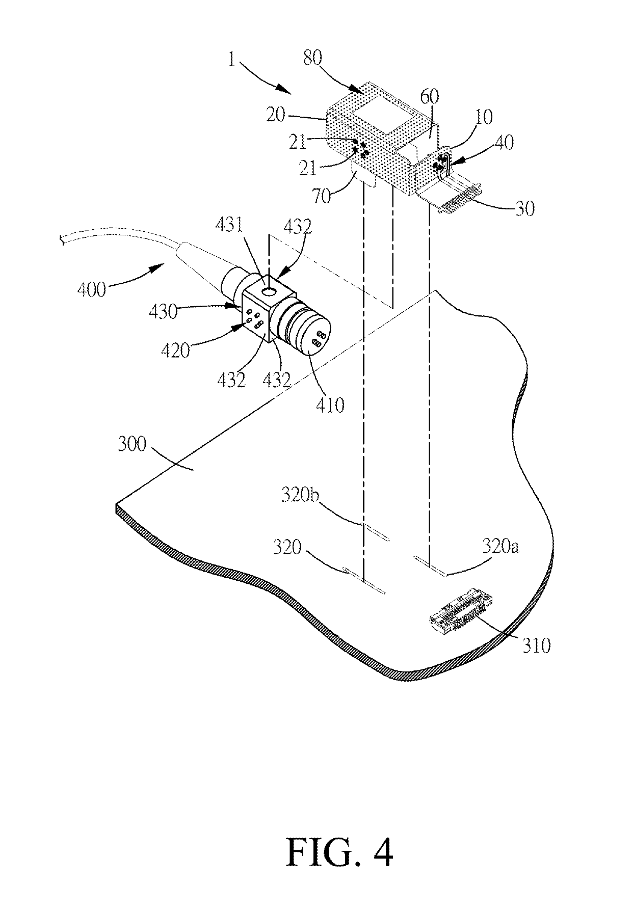
[0024]Please refer to FIG. 3 to FIG. 7 for the following paragraphs regarding a bi-directional optical sub assembly connecting structure according to one embodiment of the present invention. FIG. 3 is a schematic drawing of a bi-directional optical sub assembly connecting with a printed circuit board through a bi-directional optical sub assembly connecting structure according to one embodiment of the present invention. FIG. 4 is a schematic drawing of the bi-directional optical sub assembly, the bi-directional optical sub assembly connecting structure, and the printed circuit board when they are shown separate according to one embodiment of the present invention. FIG. 5 is a schematic drawing of the bi-directional optical sub assembly connecting structure according to one embodiment of the present inv...


PUM


Abstract

A bi-directional optical sub assembly connecting structure which is disclosed includes a first connecting plate, a second connecting plate, a connector, a first circuit, and a second circuit. The first connecting plate includes a plurality of first contacts for electrically connecting to a first transmitting end. The second connecting plate connects with the first connecting plate and includes a plurality of second contacts for electrically connecting to a second transmitting end. The connector connects with the first connecting plate for electrically connecting to a printed circuit board. The first circuit is located on the first connecting plate and electrically connected to the plurality of first contacts and the connector. The second circuit is located on the first connecting plate and the second connecting plate and electrically connected to the plurality of second contacts and the connector.

Description

BACKGROUND OF THE INVENTION1. Field of the Invention[0001]The present invention relates to a bi-directional optical sub assembly connecting structure; more particularly, the present invention relates to a bi-directional optical sub assembly connecting structure which is used for electrically connect a bi-directional optical sub assembly to a printed circuit board.2. Description of the Related Art[0002]To meet the market requirements of high-speed wire transmission, many manufacturers have developed communication equipment based on fiber optic transmission technology in recent years. As shown in FIG. 1, this kind of communication equipment has a bi-directional optical sub assembly 600, a printed circuit board 500, and a set of L-shaped pins 700. The bi-directional optical sub assembly 600 connects with a fiber optic cable to transmit electronic signals. Moreover, the bi-directional optical sub assembly 600 comprises a first transmitting end 610 and a second transmitting end 620. The ...

Claims


Application Information

Patent Timeline
Patent Type & Authority Applications(United States)
IPC IPC(8): H05K3/36H05K3/34H05K1/14H05K1/18
CPCH05K3/3494H05K1/189H05K3/363H05K1/147H05K2201/10621H05K2201/10121H05K2201/047H05K1/141H05K2201/049H05K2201/056H05K2201/048H05K2201/10189H05K3/3447
Inventor LIAO, KUO-HO
Owner XAVI TECH
Learn More