
Laminating device and laminating method

a technology of laminating device and laminating method, which is applied in the direction of sustainable manufacturing/processing, final product manufacturing, other domestic articles, etc., can solve the problems of high energy consumption, affecting power generation efficiency and assembly life, and achieve the effect of improving the quality of the laminated assembly

Inactive Publication Date: 2019-11-14
BEIJING HANERGY PV TECH CO LTD
View PDF1 Cites 0 Cited by
  • Summary
  • Abstract
  • Description
  • Claims
  • Application Information

AI Technical Summary

Benefits of technology

The present patent relates to a laminating device and method that can vacuum and heat a member to be laminated, while also effectively driving air to flow and ensure temperature uniformity, thereby preventing air bubbles and improving the quality of the laminated assembly. The technical effect is the better quality of the laminated assembly.

Problems solved by technology

However, conventional equipment used in a laminated processing of an above-mentioned assembly, such as laminators and laminated glass roller presses, has various defects, such as air bubbles occurring inside the assembly during the lamination, and has high energy consumption; some air is dissolved in an internal adhesive sheet of the assembly because it is not discharged in time so that air is easily separated out during operation of the assembly, leading to air bubbles inside the assembly, affecting power generation efficiency and life of the assembly.

Method used


Image

  • Laminating device and laminating method
  • Laminating device and laminating method
  • Laminating device and laminating method

Examples


embodiment 1

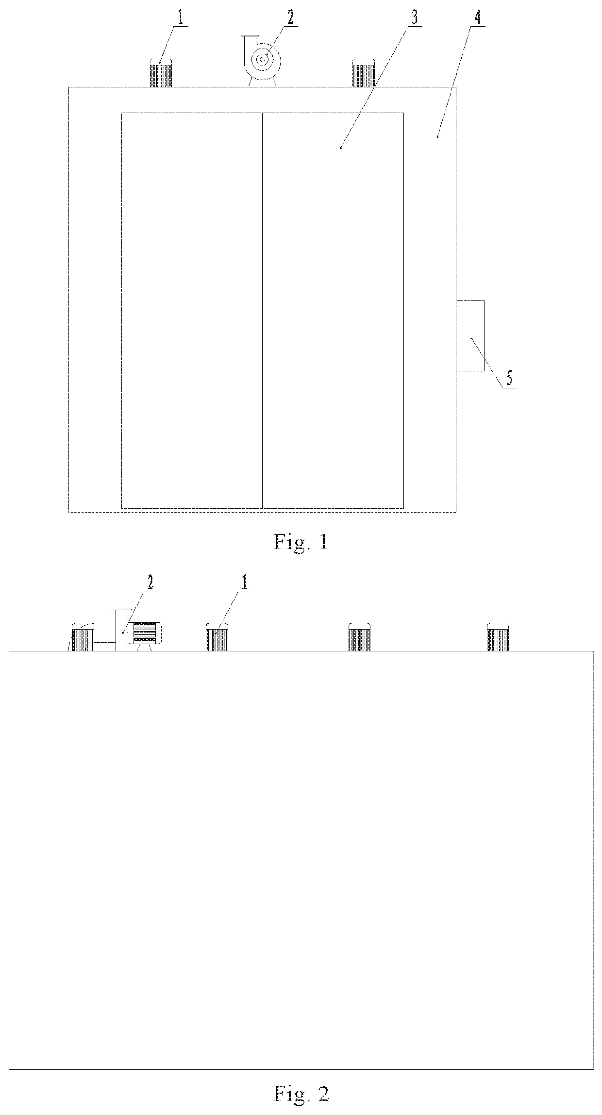
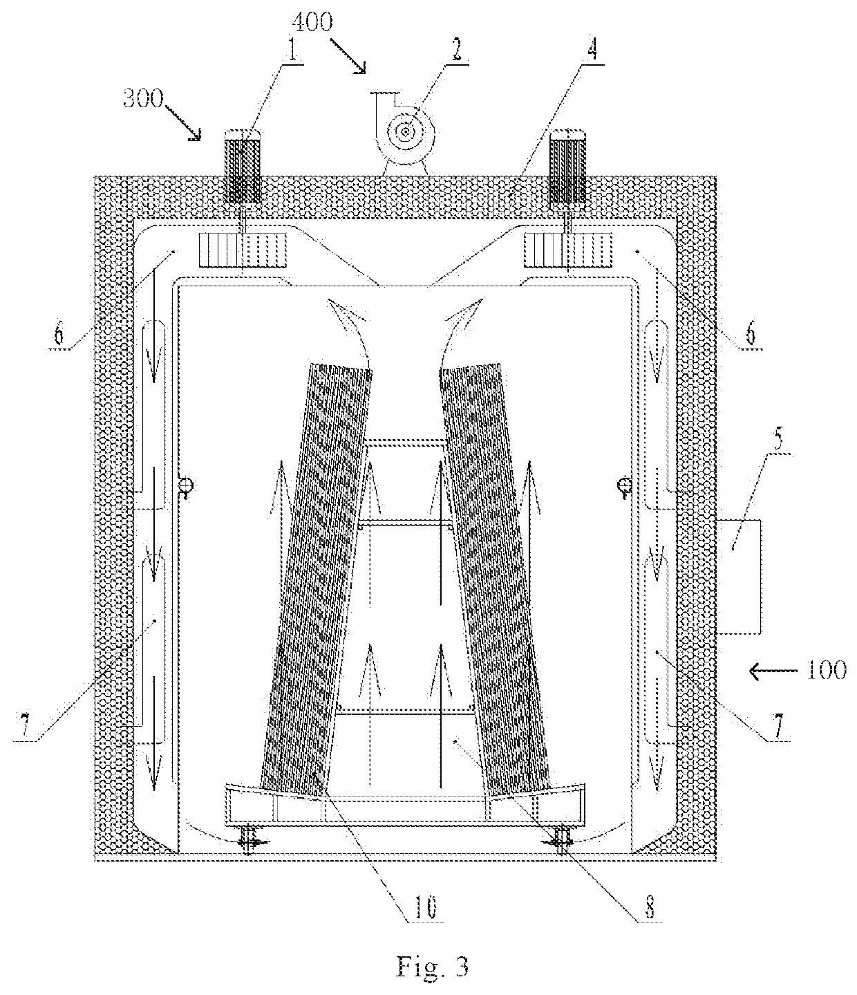
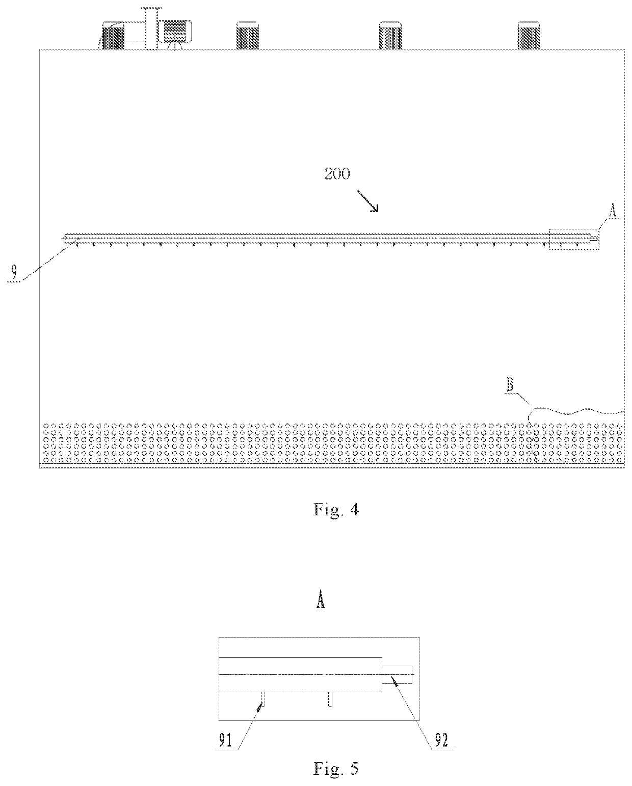
[0045]As shown in FIGS. 1 to 4, this embodiment provides a laminating device including an enclosable case body 4, a heating system 100, a vacuuming system 200 and a hot air circulation system 300. A member to be laminated 10 is placed in the case body 4, the vacuuming system 200 is configured for vacuuming the member to be laminated 10 inside the case body 4, the heating system 100 is configured for heating the member to be laminated 10 inside the case body 4, and the hot air circulation system 300 is configured for driving air in the case body 4 to flow during a heating process by the heating system 100. The member to be laminated 10 may be any two-layer or more than two-layer structure that is required to be laminated, such as a double or triple glass thin film photovoltaic assembly.

[0046]In the present embodiment, the member to be laminated 10 may be vacuumed by the vacuuming system 200 and heated by the heating system 100. Meanwhile, with the hot air circulation system 300, air ...

embodiment 2

[0068]This embodiment provides a laminating method which is applicable to not only the laminating device in Embodiment 1 but also laminating devices of other types.

[0069]As shown in FIG. 9, as a specific implementation of the present embodiment, the laminating method includes the following steps S101 and S102.

[0070]S101, vacuuming a member to be laminated; and

[0071]S102, heating the member to be laminated, and driving air around the member to be laminated to flow during the heating.

[0072]In the laminating method of the present embodiment, the member to be laminated is vacuumed and heated, while during heating the member to be laminated, the air around the member to be laminated is driven to flow, thus ensuring temperature uniformity of the air around the member to be laminated, preventing air bubbles from occurring in the member to be laminated during the laminating, and improving quality of a laminated assembly.

[0073]In an embodiment, the laminating method further comprises:

[0074]c...


PUM

PropertyMeasurementUnit
time periodaaaaaaaaaa
temperatureaaaaaaaaaa

Abstract

The present disclosure provides a laminating device including a case body, a heating system, a vacuuming system, and a hot air circulation system, a member to be laminated being placed inside the case body, the vacuuming system being configured for vacuuming the member to be laminated inside the case body, the heating system being configured for heating the member to be laminated inside the case body, and the hot air circulation system being configured for driving air in the case body to flow during heating by the heating system. Accordingly, the present disclosure further provides a laminating method.

Description

CROSS-REFERENCE TO RELATED APPLICATION[0001]This application claims the priority of Chinese Application Nos. 201810432348.6 and 201820682054.4 filed on May 8, 2018, which are hereby incorporated by reference in its entirety.TECHNICAL FIELD[0002]The present disclosure relates to but is not limited to a solar energy power generation technology, and particularly relates to but is not limited to a laminating device and a laminating method.BACKGROUND OF THE INVENTION[0003]With increasing environmental protection requirements and development in photovoltaic technologies, thin film assemblies will become the development trend of future photovoltaic products.[0004]Double or triple-glass assemblies among the thin film assemblies are required to undergo heating and vacuuming during processing to ensure that the assemblies are laminated to be an integral body. However, conventional equipment used in a laminated processing of an above-mentioned assembly, such as laminators and laminated glass r...

Claims


Application Information

Patent Timeline
Patent Type & Authority Applications(United States)
IPC IPC(8): H01L31/048B32B37/10H01L31/0445H01L31/18
CPCB32B2457/12H01L31/0488H01L31/0445B32B37/1018H01L31/1876H01L31/048Y02E10/50Y02P70/50
Inventor CHEN, DONGCHUNZHANG, XINLIU, DAWEI
Owner BEIJING HANERGY PV TECH CO LTD
Learn More