Eureka AIR delivers breakthrough ideas for toughest innovation challenges, trusted by R&D personnel around the world.

A stabilization arrangement for stabilization of an antenna mast

a technology of stabilization arrangement and antenna mast, which is applied in the direction of antenna details, wind-induced force reduction, antennas, etc., can solve the problems of mast self-oscillation, severe deformation of accuracy and sensitivity of radar arranged at the top of the mast, and the performance of e may be severely affected, so as to protect the gyroscopic stabilizer device, the effect of reducing the operation heigh

Active Publication Date: 2019-11-07
SAAB AB
View PDF5 Cites 3 Cited by
  • Summary
  • Abstract
  • Description
  • Claims
  • Application Information

AI Technical Summary

Benefits of technology

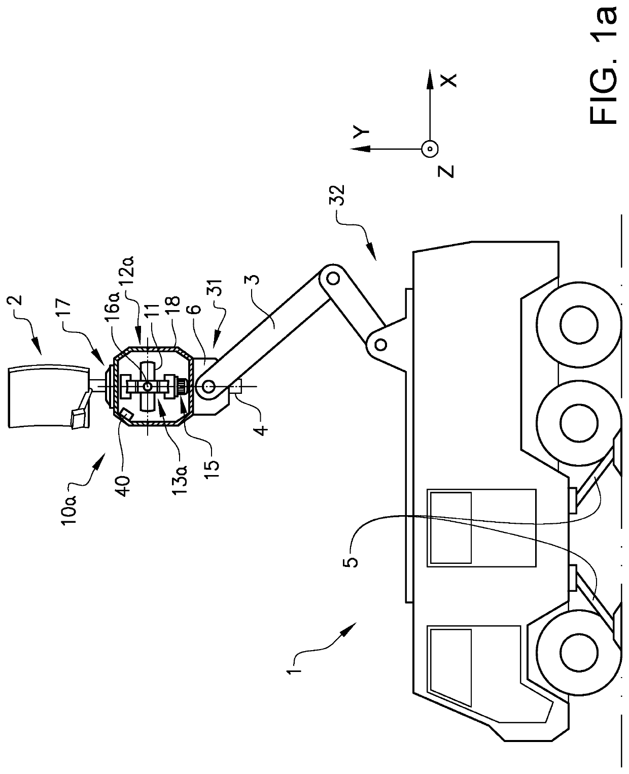
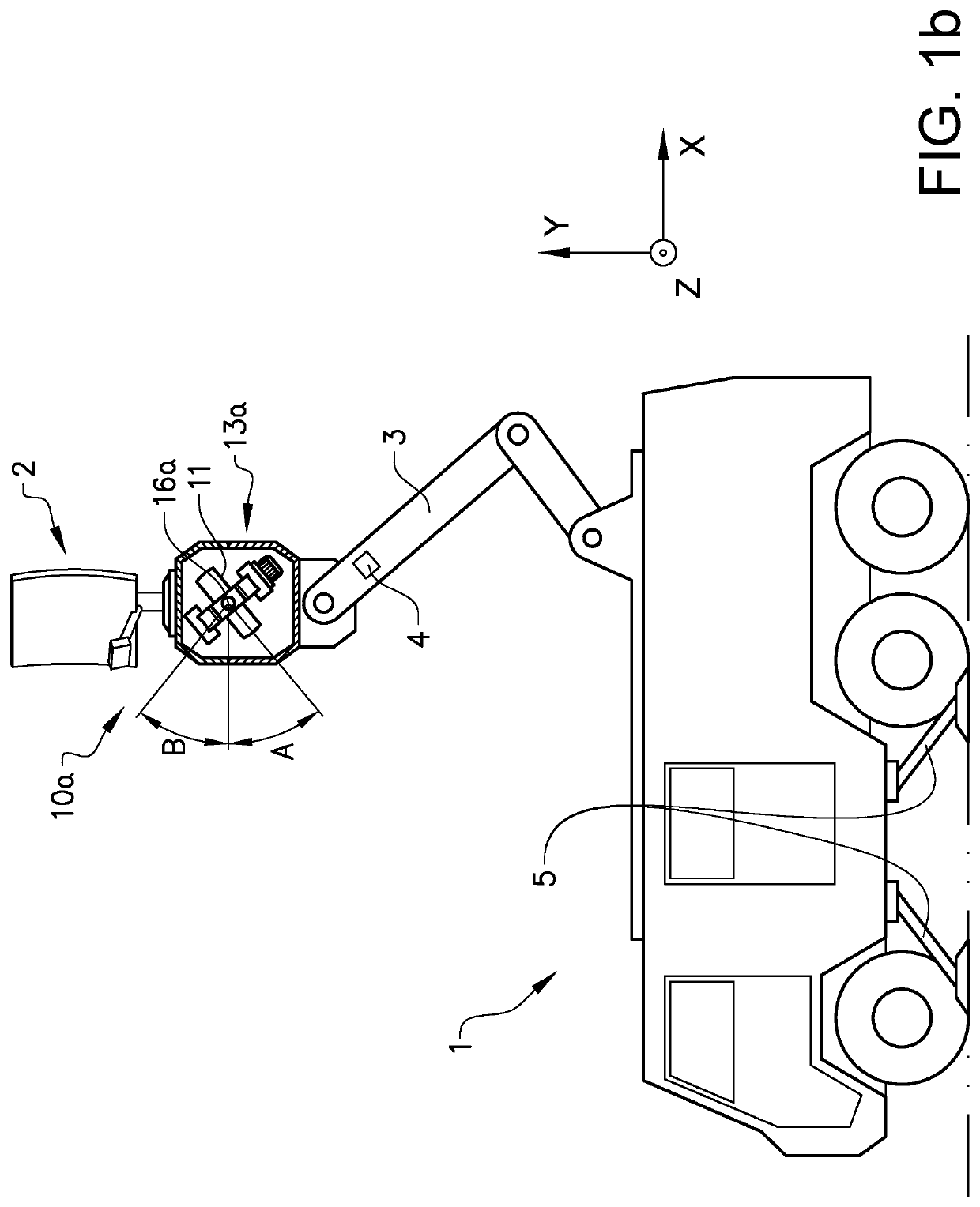
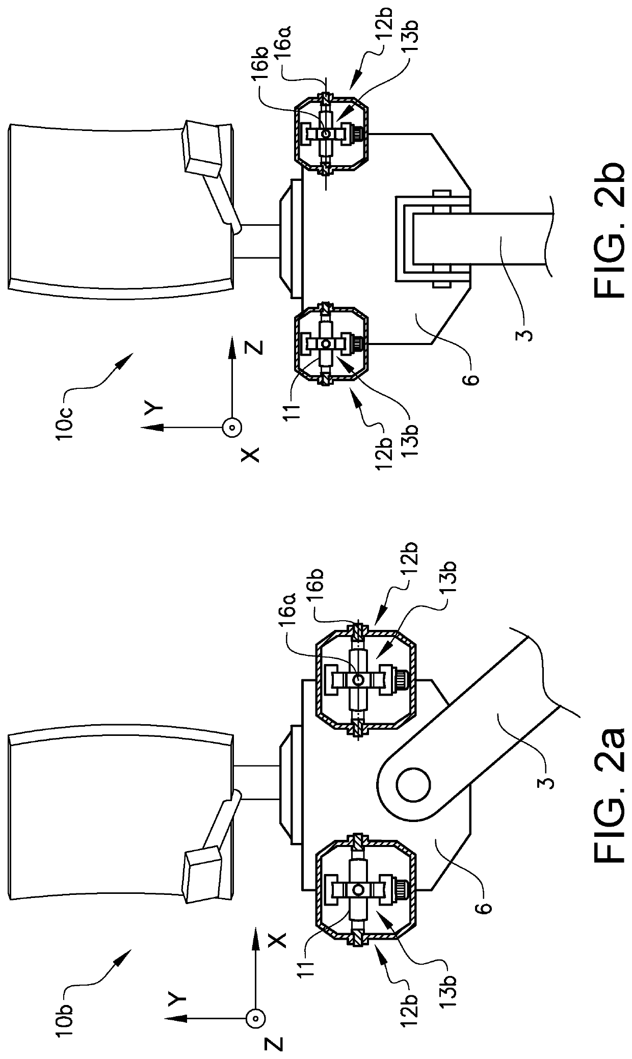
The patent aims to improve the stability of radar by reducing sideways movements in the plane perpendicular to the mast. This is achieved by applying a precessive torque to the gimbal output axis using a motor device. This control method can also counteract wind-induced oscillations, making the radar more accurate and sensitive. Additionally, it allows for higher masts and operation heights without needing vehicle supporting means.

Problems solved by technology

This may cause that the mast starts to self-oscillate.
If a mast starts to self-oscillate the top of the mast will periodically move significantly back and forth whereby the performance in terms of e.g. accuracy and sensitivity of e.g. a radar arranged at the top of the mast may be severely degraded.
Self-oscillation may, if not counteracted, not only lead to that the performance of e.g. a radar, arranged at the top of the mast, is severely deteriorated, but may also lead to shortened lifetime of the mast or to that the mast breaks.
Self-oscillations also expose the supporting or fastening structure of the mast, i.e. the structure the antenna mast is arranged to, for high loads which also might degrade and shorten the lifetime of the supporting structure.
In severe cases the supporting structure might even collapse.
Today this problem generally is addressed by, in addition to looking at the aerodynamic properties of the mast, using thicker and / or stronger goods, which often adds weight and / or cost, and by strengthening the fastening arrangements of the antenna mast, which for many applications, such as when the antenna mast is applied on a vehicle, is an unfavorable approach.

Method used


Image

  • A stabilization arrangement for stabilization of an antenna mast
  • A stabilization arrangement for stabilization of an antenna mast
  • A stabilization arrangement for stabilization of an antenna mast

Examples


Embodiment Construction

[0066]The following description of exemplary embodiments of the present invention is presented only for purposes of illustration and should not be seen as limiting. The description is not intended to be exhaustive and modifications and variations are possible in the light of the above teachings, or may be acquired from practice of various alternative embodiments of the present invention. The examples discussed herein were chosen and described in order to explain the principles and the nature of various example embodiments and its practical application to enable one skilled in the art to utilize the exemplary embodiments in various manners, and with various modifications, as are suitable for the particular use contemplated. It should be appreciated that the aspects presented herein separately may be practiced in any combination with each other unless otherwise explicitly is stated.

[0067]Reoccurring reference signs refer to corresponding elements throughout the detailed description. W...


PUM


Abstract

A stabilization arrangement (10) for stabilizing an antenna mast (3), comprising an antenna mast (3) and a gyroscopic stabilizer device (12), wherein the gyroscopic stabilizer device (12) in turn comprises a flywheel (11), a flywheel axis (14), wherein the flywheel (11) is arranged about the flywheel axis (14), and a gimbal structure (13), wherein the flywheel (11) is suspended in the gimbal structure (13) and the gimbal structure (13) is configured to permit flywheel precession or tilting about at least one gimbal output axis (16). The gyroscopic stabilizer device (12) is fixedly arranged in connection to a first end portion (31) of the antenna mast (3) and the antenna mast (3) is fastenable to a supporting structure at a second end portion (32) of the antenna mast (3), wherein the gyroscopic stabilizer device (12) is configured to reduce movements in a plane perpendicular to the extension of the antenna mast (3).

Description

TECHNICAL FIELD[0001]The present invention relates to a device for improving the stability of an extendable or elevated mast, particularly for improving radar performance of a radar system by improving the stability of the antenna mast. Although the invention will be described with respect to antenna masts, the invention is not restricted to this particular use but may also be used in order to improve the stability of other extendable masts.BACKGROUND ART[0002]High masts, such as extendable or in other way highly elevated antenna masts used for e.g. radar applications, electricity pylons or radio masts are exposed to significant forces due to continuous wind and / or wind gusts. If provided with an essentially horizontally rotating surface, such as a flat radar antenna, a parabolic disc or similar, hereinafter generally referred to as radar surface, the antenna mast is additionally exposed to oscillating forces as the surface exposed to wind varies with the rotations of the surface. T...

Claims


Application Information

Patent Timeline
Patent Type & Authority Applications(United States)
IPC IPC(8): H01Q1/12H01Q1/18
CPCH01Q1/1235H01Q1/18H01Q1/1264H01Q1/3216H01Q1/005
Inventor BLENNIUS, MARTIN
Owner SAAB AB
Why Eureka
Eureka Blog
Learn More