
Telescoping jack for lifting large capacity trucks

Active Publication Date: 2019-11-07
NORDIC MINESTEEL TECH INC
View PDF0 Cites 5 Cited by
  • Summary
  • Abstract
  • Description
  • Claims
  • Application Information

AI Technical Summary

Benefits of technology

The patent text describes a jack that can be used to lower and raise a load. The jack has a top plate that contacts the load, an intermediate plate with a channel, a base plate, and a pair of actuators that move the top plate and the intermediate plate between lowered and raised positions. The actuators are positioned on the base plate and on either side of the channel in the intermediate plate. The actuators can slide a top adapter plate between two positions on the top plate to maintain alignment with the other plates. The technical effect of this invention is a more robust and reliable jack that can safely and easily load and unload heavy loads.

Problems solved by technology

However, existing single cylinder jacks have several disadvantages.
First, they typically only lift one point or corner of the truck or load at a time.
Second, the single cylinder is often heavy and awkward to handle and as such may cause operator injuries and strains.
Third, the operator typically needs to stand under the truck while operating the jack and as such the operator may be injured by falling debris from the undercarriage of the truck.
Fourth, the operator is typically required to lock the lifted truck via safety stands or lock collars while positioned under the lifted truck, which may be dangerous.
Fifth, existing jacks are slow to operate typically requiring approximately 20 to 30 minutes per lift.
Sixth, as only one point or corner is lifted at a time by existing jacks, the lifted truck or load may become unstable when the entire front or rear is lifted at one time.
Seventh, existing jacks are often unstable when subjected to side loading, for example, when a tire is pulled off the lifted truck.

Method used


Image

  • Telescoping jack for lifting large capacity trucks
  • Telescoping jack for lifting large capacity trucks
  • Telescoping jack for lifting large capacity trucks

Examples


Embodiment Construction

[0090]In the following description, details are set forth to provide an understanding of the application. In some instances, certain structures, techniques and methods have not been described or shown in detail in order not to obscure the application.

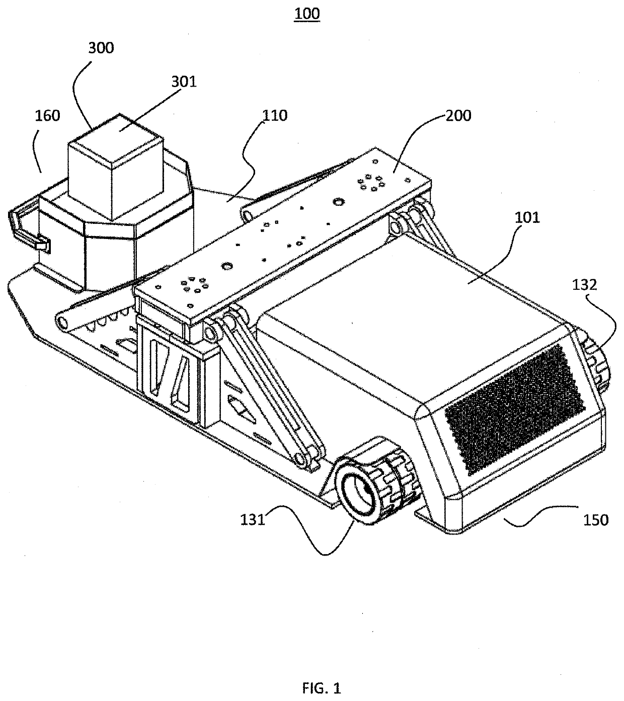
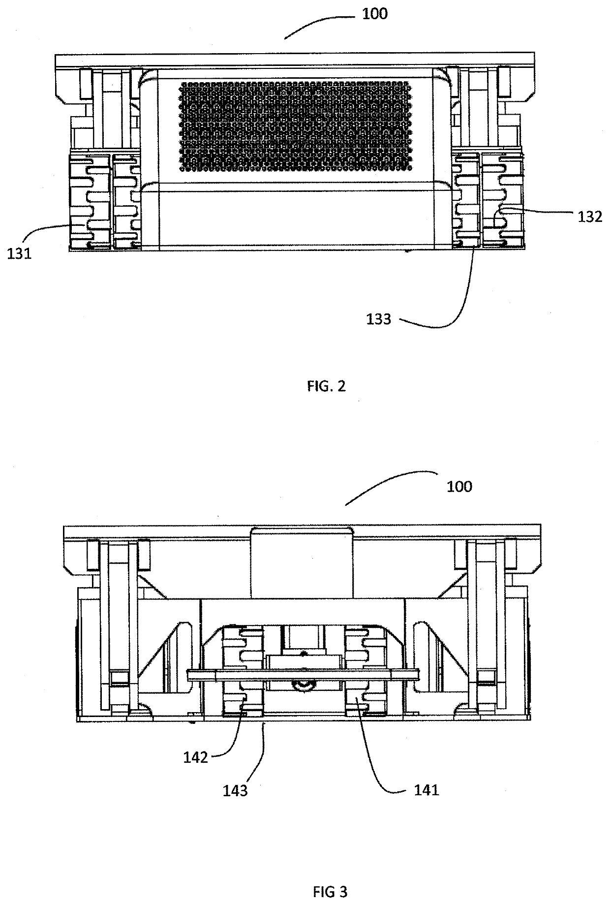
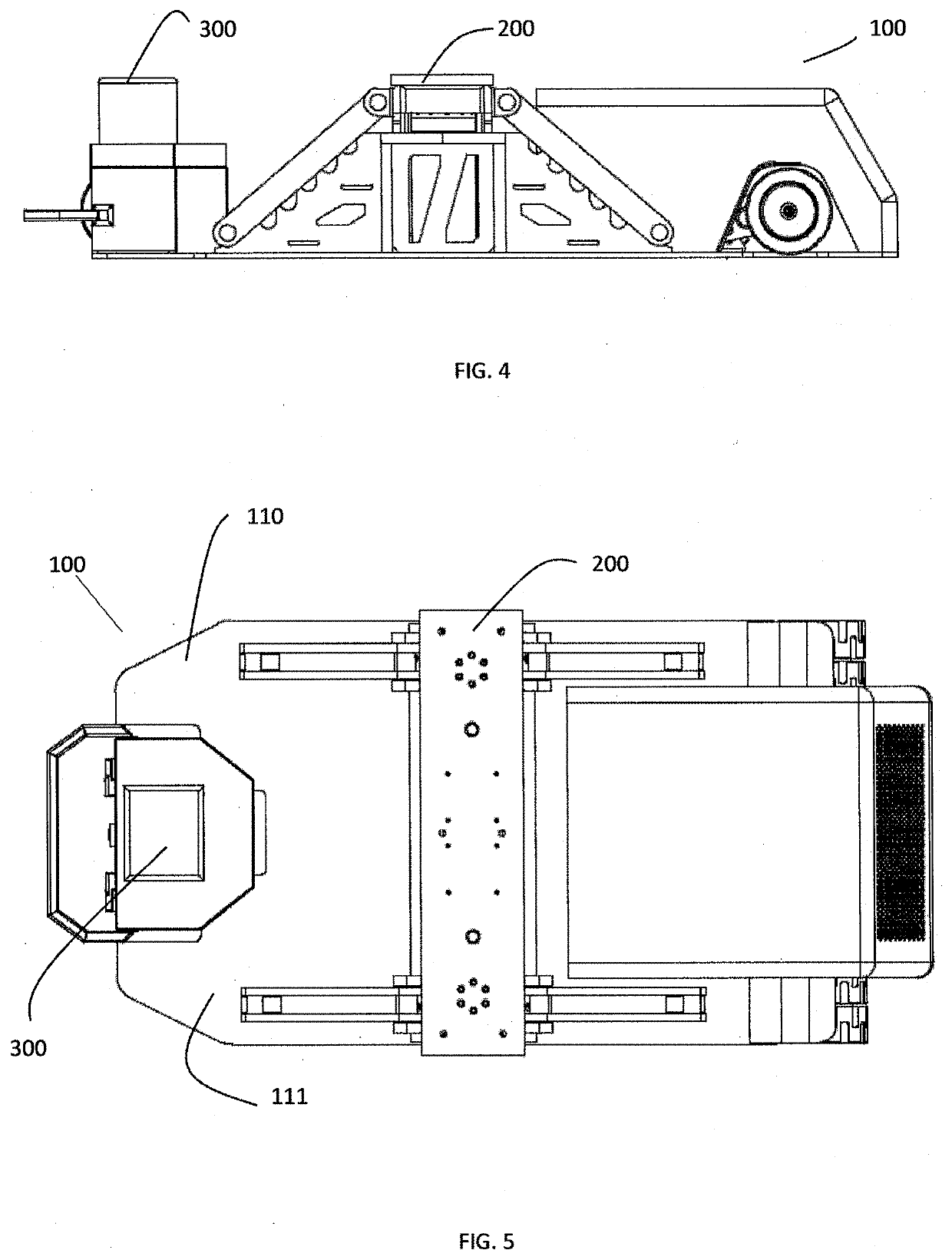
[0091]The jack 100 of the present application provides an integrated truck lifting solution. The jack 100 provides for reduced truck maintenance costs by reducing the time required to lift trucks for tire changing, repair, etc. In particular, according to one embodiment, the present application provides a jack 100 having a total collapsed height of approximately 33 inches with the ability to lift and extend linearly approximately 30 inches for a total working extend height of approximately 63 inches. This allows the jack 100 to fit under and lift a range of differently sized large capacity open pit mining haulage trucks 1000. In addition, the jack 100 has multiple visual secondary mechanical locking assemblies 810, 820, 830, 840 that ma...


PUM


Abstract

A jack, comprising: a top plate having at least one adapter block mounted thereon and adapted to contact a load; an intermediate plate; a base plate; a first pair of actuators coupled between the base and intermediate plates; and, a second pair of actuators coupled between respective lowered portions of the intermediate plate and the top plate; wherein one of the first pair of actuators is positioned on the base plate on either side of the respective lowered portions; wherein the actuators are operable to move the top and intermediate plates between respective lowered and raised positions to thereby lower and raise the load; and, wherein a top adapter plate of the at least one adapter block is operable to slide between first and second positions across the top plate as the load is raised and lowered to maintain alignment of the top, intermediate, and base plates below the load.

Description

[0001]This application is a continuation-in-part of U.S. patent application Ser. No. 15 / 589,947, filed May 8, 2017, and the entire content of such application is incorporated herein by reference.FIELD OF THE APPLICATION[0002]This application relates to the field of jacks, and more specifically, to a telescoping jack for lifting large capacity trucks, such as open pit mining haulage trucks, and the like.BACKGROUND[0003]Large capacity open pit mining haulage trucks require lifting or jacking to replace worn out or flat tires, for example. Currently, a single lifting ram or cylinder based jack is typically used for this purpose.[0004]However, existing single cylinder jacks have several disadvantages. First, they typically only lift one point or corner of the truck or load at a time. Second, the single cylinder is often heavy and awkward to handle and as such may cause operator injuries and strains. Third, the operator typically needs to stand under the truck while operating the jack an...

Claims


Application Information

Patent Timeline
IPC IPC(8): B66F5/04B66F3/28B66F7/28
CPCB66F7/28B66F5/04B66F3/28B66F3/25
Inventor DESORMEAU, WAYNEWEAVER, JEFFMATHIEU, GUY
Owner NORDIC MINESTEEL TECH INC
Learn More