
Motor controller for electric blower motors

a technology of motor controller and electric blower, which is applied in the direction of machines/engines, space heating and ventilation control systems, mechanical apparatuses, etc., can solve the problems of introducing errors in the estimation of actual airflow produced for a given motor torque and motor speed, and subjecting the estimation of actual airflow to various sources of error

Active Publication Date: 2019-10-31
REGAL BELOIT AMERICA
View PDF0 Cites 8 Cited by
  • Summary
  • Abstract
  • Description
  • Claims
  • Application Information

AI Technical Summary

Benefits of technology

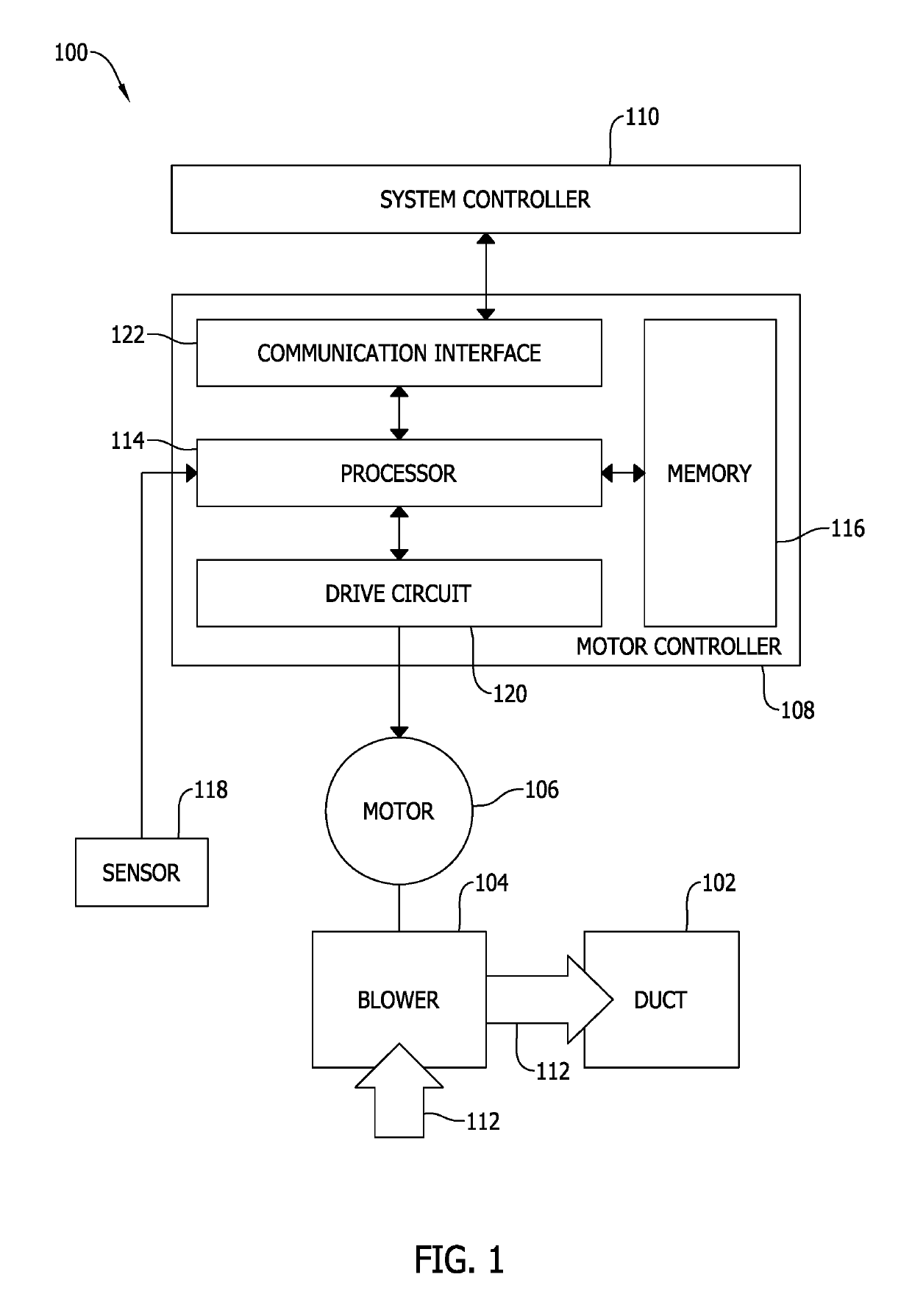
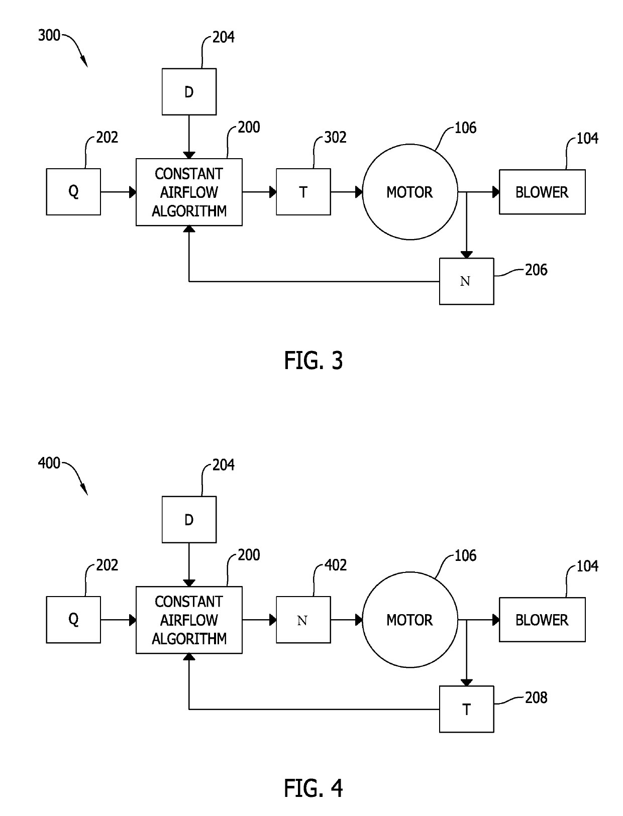
This patent describes a motor controller for an electric motor used to drive a blower to generate airflow. The motor controller includes a drive circuit and a processor. The processor is responsible for regulating the power supplied to the motor and controlling its operation. The processor uses an airflow algorithm to compute the optimal torque and speed settings for the motor based on factors like air density and the airflow rate demand. This algorithm ensures that the motor operates at the best possible efficiency and generates the necessary airflow. The motor controller is controlled by these optimal settings to achieve a constant airflow. Overall, this technology helps to achieve optimal performance and efficiency in airflow generation.

Problems solved by technology

The estimation of actual airflow produced for a given motor torque and motor speed is subject to various sources of error, including, for example, parasitic current and noise in current sensing and current regulation circuits, magnetic flux changes with temperature, effects of magnetic flux on average current during peak current regulation, variability in bearing friction, variation and drift in calibration procedures and equipment, and imperfections in drive torque production linearity.
Further, errors in estimates of actual airflow may be introduced by differences in air density, for example, in high altitude regions, where the constant airflow system is installed versus where the blower is characterized, e.g., low altitude regions.

Method used


Image

  • Motor controller for electric blower motors
  • Motor controller for electric blower motors
  • Motor controller for electric blower motors

Examples


Embodiment Construction

[0012]Embodiments of the motor controller and methods of operating an electric blower motor for a constant airflow system described herein provide improved characterization of the electric blower motor based on motor torque, motor speed, airflow, and air density. In a torque-controlled implementation, for example, the characterization embodied in the motor controller and methods described herein produces one or more torque-speed-airflow data points that define a surface that characterizes the operating profile of the constant airflow system. That surface is then approximated by a polynomial, airflow algorithm, or formula, that defines motor torque (T) as a function of air density (D), motor speed (N), and airflow rate demand (Q). Likewise, in a speed-controlled implementation, for example, the characterization embodied in the motor controller and methods described herein again produces numerous torque-speed-airflow data points that define a surface that characterizes the operating p...


PUM


Abstract

A motor controller for an electric motor is provided, including a drive circuit and a processor. The drive circuit regulates power supplied to a stator of the electric motor to turn a rotor and blower to generate an airflow. The processor receives an air density, an airflow rate demand, and at least one of a measured torque and a measured speed of the electric motor. The processor computes one of a torque set point and a speed set point for the electric motor using an airflow algorithm and based on the air density, the airflow rate demand, and the at least one of the measured torque and the measured speed. The processor controls the drive circuit based on the one of the torque set point and the speed set point to supply electrical power to the electric motor and to operate the blower to generate the airflow.

Description

BACKGROUND[0001]The field of the disclosure relates generally to a motor controller for electric blower motors and, more specifically, a motor controller that enables approximately constant airflow production.[0002]At least some electric motors are torque-calibrated when manufactured to ensure the torque output at the drive shaft of the electric motor matches the torque commanded. At least some electric motors, particularly electric motors driving blowers, such as a forward curve blower, are further calibrated to produce approximately a constant airflow during operation in either a torque-control mode or a speed-control mode. Such a calibration, or characterization, quantizes airflow output for a given speed and torque output when driving the blower. The actual airflow output can vary according to the blower construction, duct or other airflow restriction into which the airflow is directed.[0003]Constant airflow heating, ventilation, and air conditioning (HVAC) systems improve therm...

Claims


Application Information

Patent Timeline
IPC IPC(8): F04D27/00F24F11/77F24F11/63F24F11/30F24F11/75
CPCF04D27/004F24F11/77F24F2110/30F05D2270/024F24F11/30F24F11/75F24F11/63F05D2270/335F05D2270/304F04D27/001F05D2270/3061Y02B30/70
Inventor YANG, BINBEIFUS, BRIAN L.BECERRA, ROGER C.
Owner REGAL BELOIT AMERICA
Learn More