
Well service pump systems and related methods

a well service pump and plunger technology, applied in the direction of piston pumps, borehole/well accessories, surveys, etc., can solve the problems of reducing the stroke length of the plunger, reducing the size of the trailer mounted frac unit, and causing the failure rate of the current frac pump fluid end,

Pending Publication Date: 2019-10-31
AMERIFORGE GRP
View PDF0 Cites 122 Cited by
  • Summary
  • Abstract
  • Description
  • Claims
  • Application Information

AI Technical Summary

Benefits of technology

The present patent is about a well service pump system that can deliver working fluid to a well at high pressure. The system includes at least two working fluid pump assemblies, each with a plunger rod and a hydraulic ram cylinder. The hydraulic ram cylinder has two hydraulic ports and a piston rod that is coupled to the plunger rod of the working fluid end cylinder. The system also includes a motor to drive the bi-directional pumps, which compensates for leakage in the system. The system can deliver the working fluid to the well by actuating the hydraulic ram cylinder to move the plunger rod and transfer mechanical energy from the motor to the pumps. The system can also include an inlet and outlet check valve to control the flow of the working fluid. The technical effects of the system include high-pressure delivery of working fluid to the well and efficient compensation for leakage.

Problems solved by technology

There are a number of known problems with the prior art plunger pumps of the type under consideration.
As a result, this necessarily means that the frac units which are trailer mounted will be restricted in size by the applicable DOT rules and regulations.
However, reducing the stroke length of the plungers is not an ideal solution to the problem and, in fact, offers a number of disadvantages in the design.
This is due to the fact that there is a tremendous failure rate in current frac pump fluid ends, due to cyclic fatigue.
The increased failure rate results from increased demand placed upon today's frac pumps, as compared to the practice in prior years.
This type of operation may exceed the intended design limits of the units.
However, these designs still suffer from all of the problems of having the frac pump mounted at a right angle to the engine, transmission and driveline.
They also fail to reduce the mechanical complexity of the system and, in fact, likely increase the complexity.
With prior art designs, it will be very difficult to increase the plunger stroke length much more than 10 to 12 inches.
This can put frac pumps in violation of DOT standards regarding the width of the trailer mounted frac unit, since the pump sits at a right angle to the engine, transmission and driveline.

Method used


Image

  • Well service pump systems and related methods
  • Well service pump systems and related methods
  • Well service pump systems and related methods

Examples


Embodiment Construction

[0033]The following drawings illustrate by way of example and not limitation. For the sake of brevity and clarity, every feature of a given structure is not always labeled in every figure in which that structure appears. Identical reference numbers do not necessarily indicate an identical structure. Rather, the same reference number may be used to indicate a similar feature or a feature with similar functionality, as may non-identical reference numbers. The figures are drawn to scale (unless otherwise noted), meaning the sizes of the depicted elements are accurate relative to each other for at least the embodiment depicted in the figures.

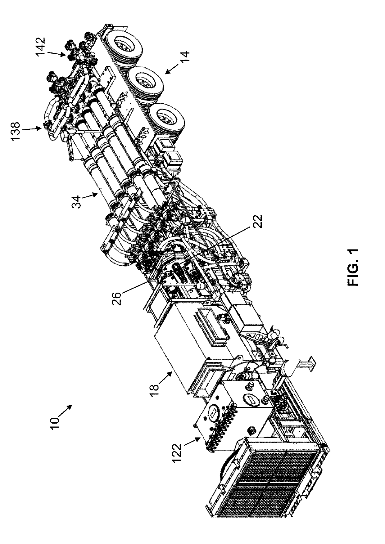
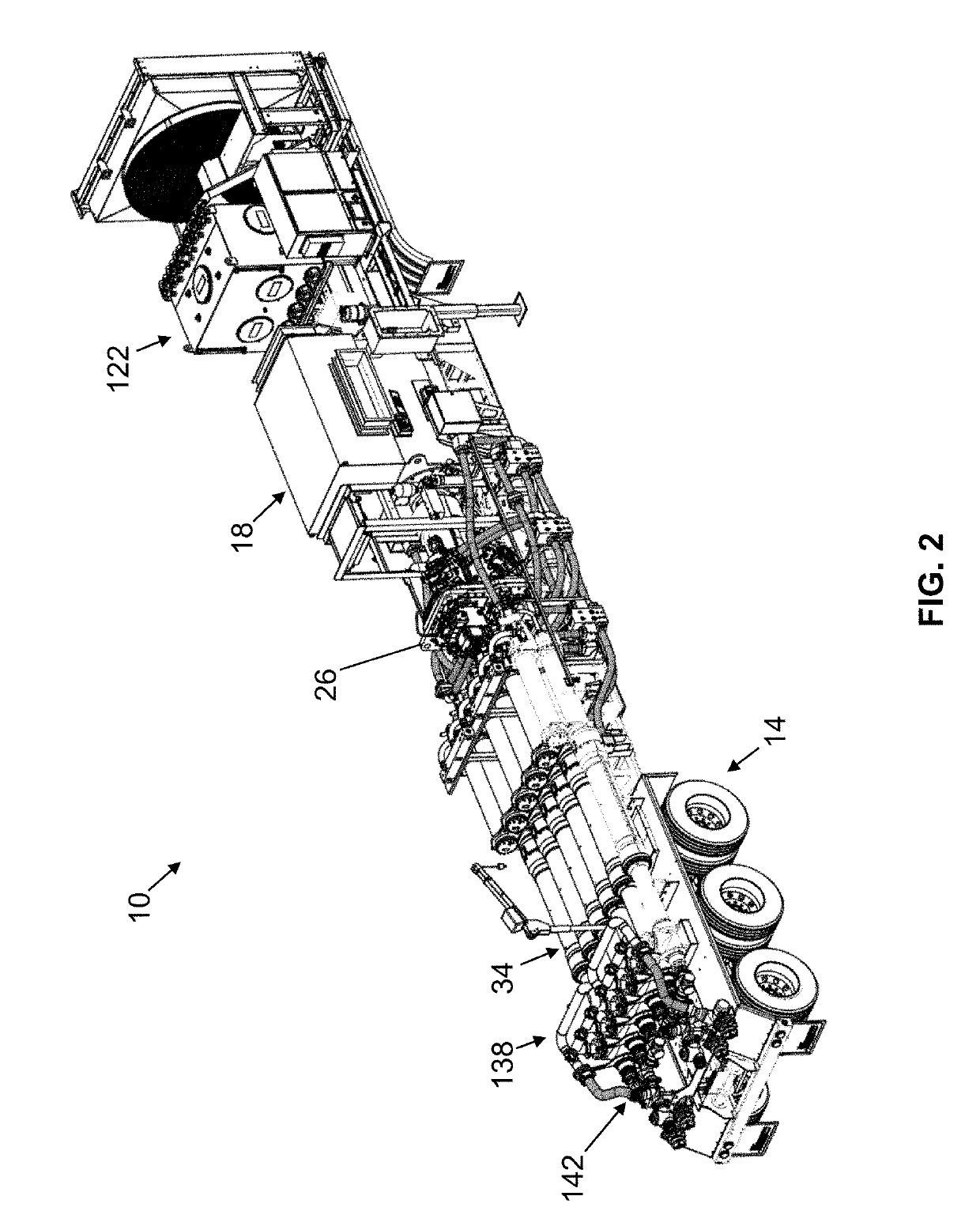
[0034]Referring now to the figures, and more particularly, to FIGS. 1 and 2, shown therein and designated by reference numeral 10 is an embodiment of the present well service pump systems for delivering working fluid at high pressure to a well. As shown, system 10 can be coupled to and carried by a vehicle 14 (e.g., a truck trailer) for transportati...


PUM


Abstract

A well service pump system supplies high pressure working fluid to a well. The pump system includes a closed-loop hydraulic circuit for actuating a plurality of working pump assemblies. The pump system is powered by a motor, which transfers mechanical energy to a plurality of pumps, which, in turn, provide hydraulic fluid to operate hydraulic ram cylinders, and thereby operate the working pump assemblies. Each of the polished rods of the hydraulic ram cylinders is connected axially to a plunger rod end of the working fluid end cylinder to operate the working pump assembly.

Description

CROSS-REFERENCE TO RELATED APPLICATIONS[0001]This application claims priority to U.S. Provisional Application No. 62 / 664,072, filed Apr. 27, 2018, the entire contents of which application are specifically incorporated by reference herein without disclaimer.FIELD OF INVENTION[0002]The present invention relates generally to pumping assemblies used for well servicing applications, most particularly pumping assemblies used for well fracturing operations.DESCRIPTION OF RELATED ART[0003]Oil and gas wells require services such as fracturing, acidizing, cementing, sand control, well control and circulation operations. All of these services require pumps for pumping fluid down the well. The type of pump that has customarily been used in the industry for many years is a gear driven plunger type, which may be referred to as a “frac pump.” The pump is often powered by a diesel engine, typically 2,000 bhp or larger, that transfers its power to a large automatic transmission. The automatic transm...

Claims


Application Information

Patent Timeline
Patent Type & Authority Applications(United States)
IPC IPC(8): E21B4/14E21B47/00E21B43/12
CPCE21B43/129E21B4/14E21B47/0008E21B44/005F04B9/113F04B17/06F04B23/06F04B53/008F04B2205/501E21B47/009
Inventor GABLE, TOMSMITH, GARRETTBURNETT, SHELTONMARTIN, ERICMEYER, LYLE
Owner AMERIFORGE GRP
Learn More