
Fog machine with continuous water supply

a technology of fog machine and water supply point, which is applied in the direction of liquid spraying apparatus, stage arrangements, theatre/circus, etc., can solve the problems of difficult to find the water supply point to successfully supply water, adversely affecting the fog generating effect, and inability to achieve continuous fog spray

Inactive Publication Date: 2019-10-24
GUANGZHOU DJPOWER ELECTRONICS TECH CO LTD
View PDF0 Cites 7 Cited by
  • Summary
  • Abstract
  • Description
  • Claims
  • Application Information

AI Technical Summary

Benefits of technology

The present invention provides a water tank with a water reservoir that automatically controls the water supply based on the water level in the tank. This prevents fog from flowing into the reservoir and affecting the water adding process, allowing for continuous fog generation without stopping the process. The coverplate of the reservoir can be directly opened for adding water without interrupting the fog generation process.

Problems solved by technology

In this configuration, high water level will adversely affect fog generating effect, while low water level means a pool water storage capacity, which requires frequent water re-supply.
Since the water tank and the fog generating chamber is in the same chamber, a large amount of fog as generated will flow out when the water re-supply window is opened, making it difficult to find out the water supply point to successfully supply water.
Therefore, a continuous fog spray cannot be achieved.
Frequent water re-supply requires frequent stop of fog spray, such that a stage effect with continuous fog spray can hardly be obtained.

Method used


Image

  • Fog machine with continuous water supply
  • Fog machine with continuous water supply
  • Fog machine with continuous water supply

Examples


Embodiment Construction

[0018]The embodiments of the invention will be further described in combination with the drawings.

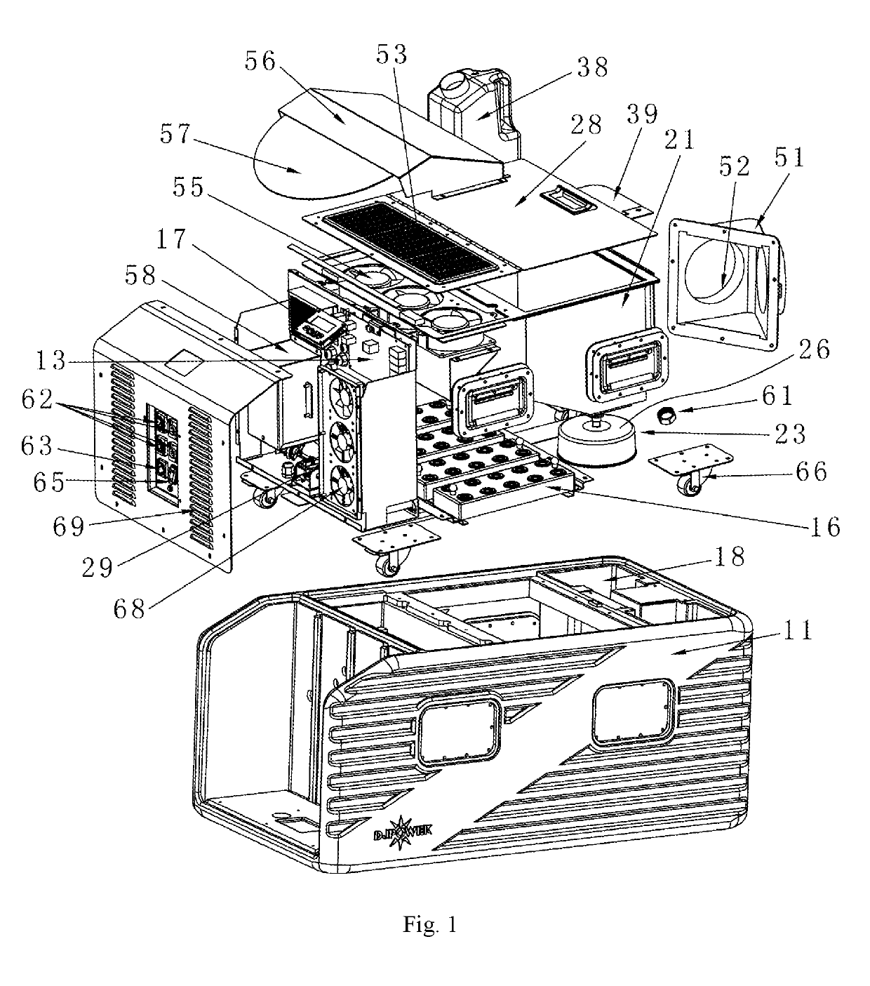
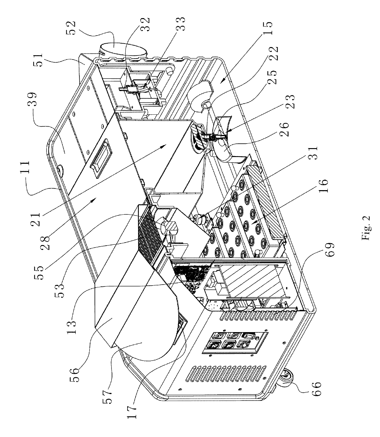
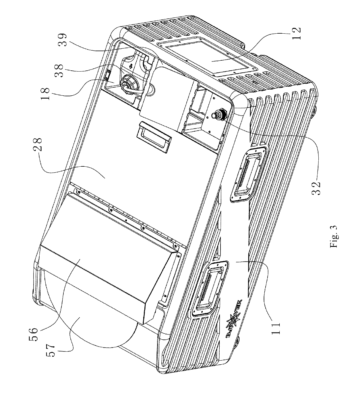
[0019]As shown in FIGS. 1, 2, and 3, the present invention provides a fog machine with continuous water supply, comprising: a main body 11 provided with a fog outlet 12, a circuit board 13 provided inside the main body, a water tank 15 provided at the bottom of the main body, a fog generator 16 provided in the water tank 15 and electrically connected with the circuit board 13, a water reservoir 21 provided above the water tank, a water filling port 22 provided at the bottom of the water reservoir 21, and a water filling switch 23 provided at the water filling port and controlled by the water level of the water tank, wherein the space above the water tank is in communication with the fog outlet 12. The water reservoir 21 is provided above the water tank 15 and the water filling switch 23 controls the water in the water reservoir 21 flowing into the water tank 15, wherein the opening and ...


PUM


Abstract

A fog machine with continuous water supply is disclosed, comprising: a main body provided with a fog outlet, a circuit board inside the main body, a water tank at a bottom of the main body, a fog generator in the water tank and electrically connected with the circuit board, a water reservoir above the water tank, a water filling port at a bottom of the water reservoir, and a water filling switch at the water filling port and controlled by a water level of the water tank, wherein the space above the water tank is in communication with the fog outlet. The water filling switch controls the water in the water reservoir flowing into the water tank, wherein the opening and closing of the switch depends on the water level of the water tank. If the level becomes high, the switch is automatically closed and water supply is stopped, and if the level becomes low, the switch is automatically opened and water supply is started. The water tank where fog is generated is separated from the water reservoir, such that the fog will not flow into the water reservoir and thus will not influence adding water into the water reservoir during the fog generating process. Therefore, adding water does not require stopping the machine and does not influence the fog generating process, and therefore the fog generating process can be conducted continuously.

Description

TECHNICAL FIELD[0001]The present invention relates to a fog machine, and particularly to a fog machine with continuous water supply.BACKGROUND[0002]In conventional fog machines, the fog generating chamber is formed by the entirety of the inner chamber of its main body. In this configuration, high water level will adversely affect fog generating effect, while low water level means a pool water storage capacity, which requires frequent water re-supply. Since the water tank and the fog generating chamber is in the same chamber, a large amount of fog as generated will flow out when the water re-supply window is opened, making it difficult to find out the water supply point to successfully supply water. In this case, the fog spraying has to be stopped to allow for water re-supply, and then re-started after the water re-supply is completed. Therefore, a continuous fog spray cannot be achieved. Frequent water re-supply requires frequent stop of fog spray, such that a stage effect with cont...

Claims


Application Information

Patent Timeline
Patent Type & Authority Applications(United States)
IPC IPC(8): A63J5/02
CPCA63J5/025B05B12/081B05B17/0607
Inventor XU, HUI
Owner GUANGZHOU DJPOWER ELECTRONICS TECH CO LTD
Learn More