Decoration ribbon

a ribbon and decoration technology, applied in the field of decoration ribbons, can solve the problem that the decoration ribbon cannot be applied in a door leaf having a larger dimension, and achieve the effect of tight sleeves

Inactive Publication Date: 2019-10-17
KUAN HUO FENG HSIA
View PDF0 Cites 0 Cited by
  • Summary
  • Abstract
  • Description
  • Claims
  • Application Information

AI Technical Summary

Benefits of technology

The present invention provides a decoration ribbon that uses a fastening band instead of an elastic band for a more secure and tight fit. The ribbon has an adhering and fastening area that can be adjusted for a snug fit on different plates, such as cabinet doors, window frames, or door leaves. This prevented the ribbon from becoming loose and falling off due to elastic fatigue.

Problems solved by technology

Moreover, because of the limitation of the elastic stretching range of the above-mentioned elastic band 20, the decoration ribbon is unable to be applied in a door leaf having a larger dimension, for example a compartment door of a kitchen; as such, the above-mentioned disadvantages shall be seriously concerned by the skilled people in the art.

Method used


Image

  • Decoration ribbon
  • Decoration ribbon
  • Decoration ribbon

Examples


first embodiment

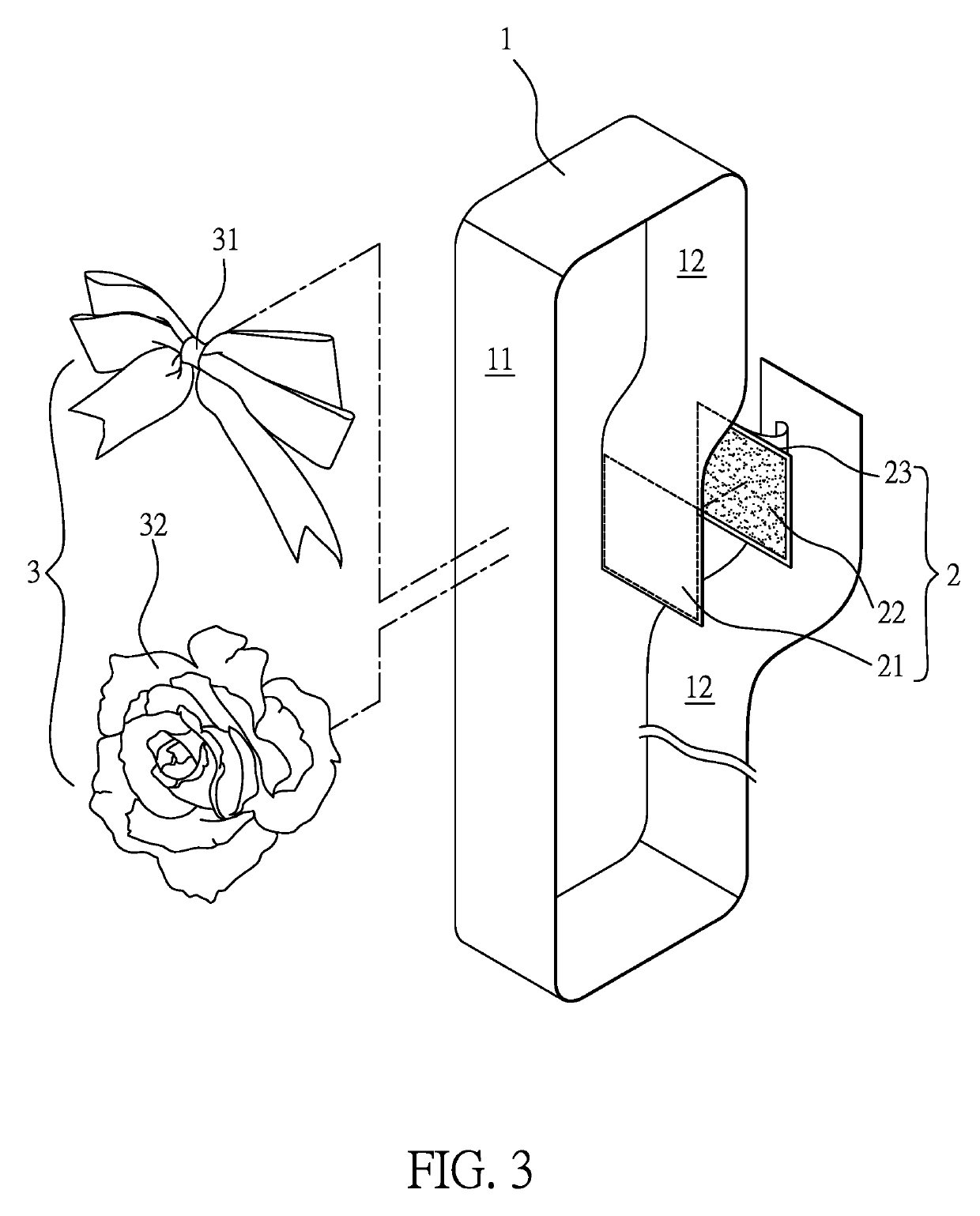
[0023]A rear surface of the at least one decorative object 3 and the first surface 11 of the ribbon member 1 are oppositely disposed with a second fibriform pile fabric structure 51 and a second micro-fibriform loop fabric structure 52 of a second fastening band 5, the at least one decorative object 3 can be combined on the first surface 11 of the ribbon member 1 with a adhering and fastening means, thus the decorative object 3 can be rapidly replaced, for example the bow-like decorative object 31 being replaced by the flower-like decorative object 32. In other words, a user can replace the decorative object 3 matched with the different atmospheres of different holidays according to the different holidays, thereby increasing the atmospheres of different holidays. What shall be addressed is that the replacement of the decorative object 3 can also be applied in the first embodiment so as to expand the applicable range.

[0024]Moreover, if the decoration ribbon disclosed in the first emb...

second embodiment

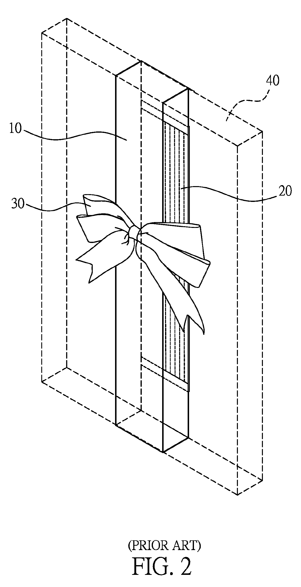
[0025]Accordingly, when the decoration ribbon disclosed in the second embodiment is assembled with the plate to be decorated 40 having a larger dimension, please refer to FIG. 6, the ribbon member 1 and the extension band 6 can be arranged to be tightly adjacent to the plate to be decorated 40, so that a situation of being loosened can be prevented.

[0026]Moreover, with the overlapped adhering and fastening area between the first fibriform pile fabric structure 21 and the extending micro-fibriform loop fabric structure 72 and between the first micro-fibriform loop fabric structure 22 and the extending fibriform pile fabric structure 71, the wrapping tightness of the ribbon member 1 and the extension band 6 to the plate to be decorated 40 can be properly adjusted.

[0027]According to this embodiment, the first fibriform pile fabric structure 21 and the first micro-fibriform loop fabric structure 22 are respectively fastened on the second surface 12 and the first surface 11 of the ribbon...


PUM


Abstract

A decoration ribbon comprises a ribbon member formed with a first surface and a second surface, a first fastening band and at least one decorative object; the first surface or the second surface at one end of the ribbon member is disposed with a first fibriform pile fabric structure or a first micro-fibriform loop fabric structure of the first fastening band; the second surface or the first surface at another end of the ribbon member is disposed with the first micro-fibriform loop fabric structure or the first fibriform pile fabric structure of the first fastening band, and the at least one decorative object is combined on the first surface of the ribbon member; when the first fibriform pile fabric structure is adhered and fastened with the first micro-fibriform loop fabric structure, the ribbon member is formed as an annular member for wrapping a plate to be decorated.

Description

BACKGROUND OF THE INVENTION1. Field of the Invention[0001]The present invention relates to a decoration ribbon, especially to a decoration ribbon used for decorating a cabinet door, a door leaf or a window.2. Description of Related Art[0002]In the western countries, for example the United States of America, at least one decoration ribbon would be used for being sleeved on a cabinet door, a door leaf or a window for increasing the atmosphere of certain holiday such as Christmas, so that the regular cabinet door, the door leaf or the window can be provided with a better visual effect for matching the holiday atmosphere.[0003]Please refer to FIG. 1, which is perspective view illustrating a conventional decoration ribbon; the decoration ribbon includes a ribbon member 10, an elastic band 20 and a decorative object 30. The ribbon member 10 is formed as an elongated strip member, and two distal ends 101 thereof are connected to the elastic band 20 with a sewing means, so that an annular s...

Claims


Application Information

Patent Timeline
Patent Type & Authority Applications(United States)
IPC IPC(8): D04D9/00A41G1/00D04D7/10
CPCD04D7/10D04D9/00A41G1/00
Inventor KUAN, HUO FENG HSIA
Owner KUAN HUO FENG HSIA
Why Eureka
Try Eureka