
Gas sensor with a configurable heating element, and methods exploiting the configurability

a technology of gas sensors and heating elements, applied in the field of gas sensors, can solve the problems of significant deviations between the measurements taken by individual devices, differences in thickness and homogeneity of the membrane and heating material, and heating of gas-sensitive layers to different temperatures, so as to reduce the time required to acquire measurement data characterizing the response of gas-sensitive layers at different temperatures and increase the speed of acquisition of measurement data at different temperatures

Active Publication Date: 2019-10-10
ALPHA MOS
View PDF0 Cites 1 Cited by
  • Summary
  • Abstract
  • Description
  • Claims
  • Application Information

AI Technical Summary

Benefits of technology

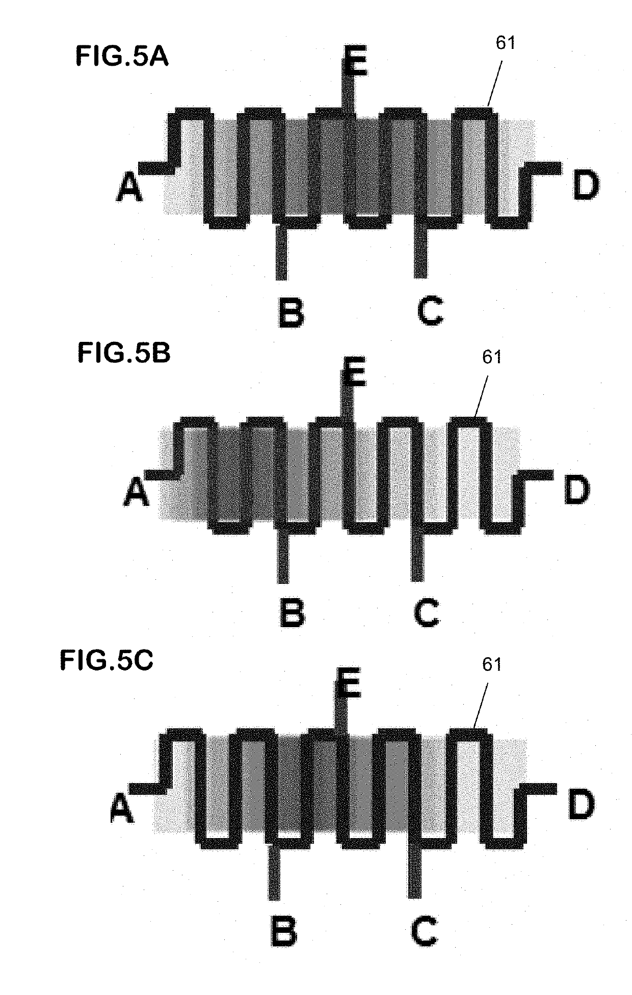
The heating element in these gas sensors allows for individual calibration and compensation for physical characteristics variations during manufacturing. The heating element can be set to heat the gas-sensitive layer to a target design value even if its physical characteristics vary due to manufacturing tolerances. This embodiment also allows for simultaneous determination of the gas-sensitive layer's characteristics at different temperatures using multiple measurement electrodes. This reduces the time required to acquire data and avoids the need for an array of gas sensors. The speed of acquisition at different temperatures is increased and the number of data points is multiplied by the number of gas sensors in the array.

Problems solved by technology

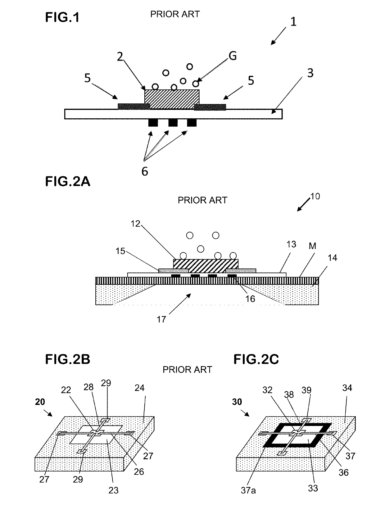
However, the manufacturing process often results in variations in physical characteristics between gas-sensors of a same batch, for example there may be differences in thickness and homogeneity of the membrane and of the heating material.
As a result of such differences, application of a given voltage to the heater tracks of different individual sensors may result in heating of the gas-sensitive layers to different temperatures.
This may lead to significant deviations between the measurements that are taken by the individual devices.
Moreover, a measurement obtained from a single gas sensor at a single operating temperature may be insufficient to enable a gas to be identified with a desired degree of certainty.
Unfortunately, such an approach tends to increase the period of time required for detection of the gas.
Unfortunately, such an approach tends to increase the size and cost of the device, as well as increasing the power consumption.

Method used


Image

  • Gas sensor with a configurable heating element, and methods exploiting the configurability
  • Gas sensor with a configurable heating element, and methods exploiting the configurability
  • Gas sensor with a configurable heating element, and methods exploiting the configurability

Examples


Embodiment Construction

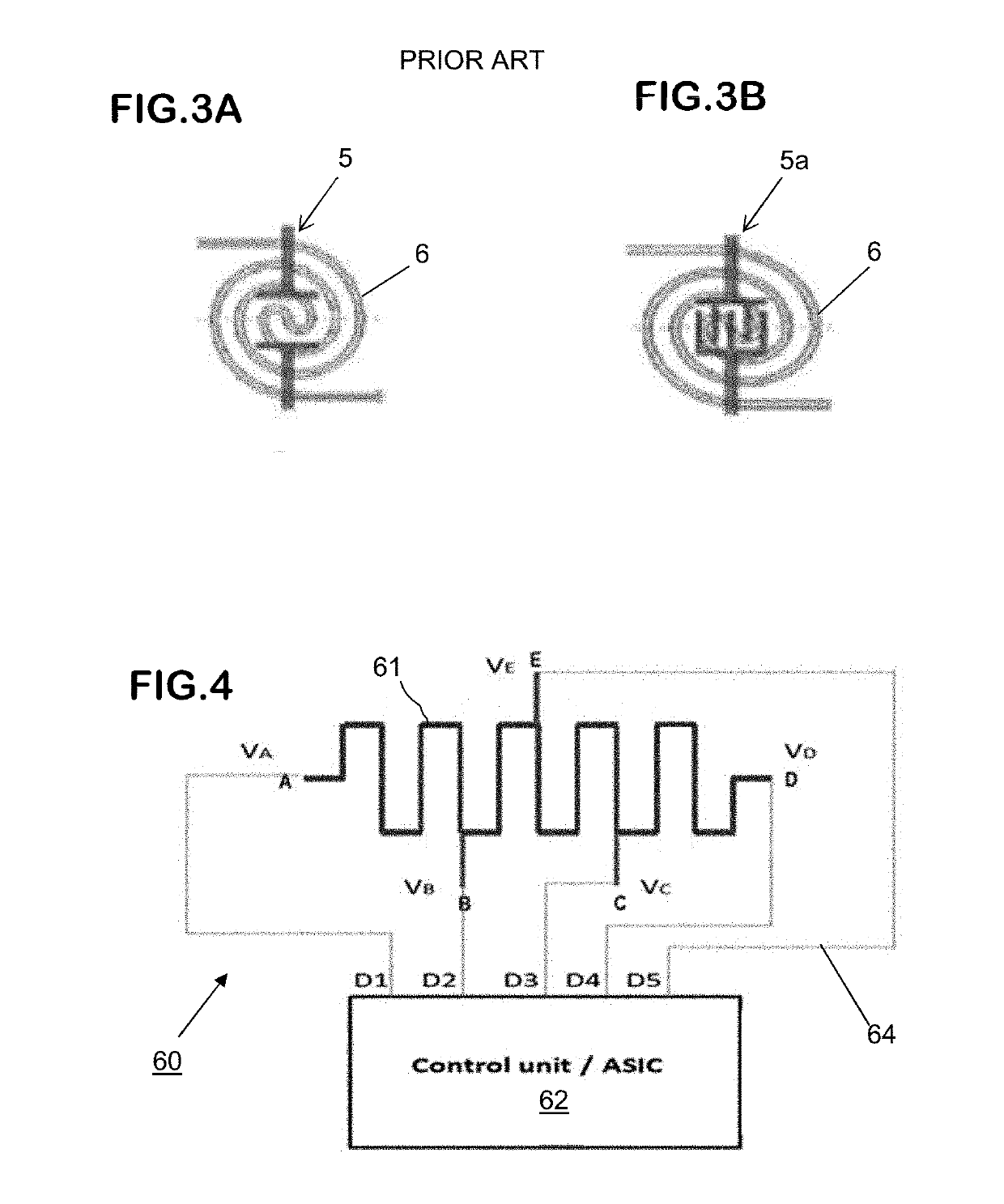
[0074]FIG. 4 illustrates an example of a heater assembly 60 that may be used in a gas sensor according to a first embodiment of the invention. FIG. 4 does not show details of the remainder of the gas sensor (e.g. gas-sensitive layer, measurement electrodes to detect the reaction of the gas-sensitive layer to gas species, and so on).

[0075]In the heater assembly 60 of FIG. 4, a heating element in the form of an electrically-conductive heater track 61 is connected to a control unit 62 by conductors 64. The control unit 62 is connected to a source of electrical power (not shown) of any convenient type, e.g. a battery, a mains power source, and so on. If desired, one or more temperature sensors may be associated with the heater assembly to detect the actual temperature(s) produced by the heater track at one or more locations of interest.

[0076]The heater track 61 may be formed of any convenient material, such as a conductive material of the usual types employed in heating elements of gas ...


PUM

PropertyMeasurementUnit
temperatureaaaaaaaaaa
angleaaaaaaaaaa
resistanceaaaaaaaaaa

Abstract

In a gas sensor having a gas-sensitive layer and a heating element to heat the gas-sensitive layer, the heating element comprises a heater track having first and second outer electric terminals and at least one inner electric terminal located between the outer electric terminals. The gas sensor includes a control unit configured to control the electric potentials that are applied to the electric terminals during use, and the control unit is configured to be capable of varying the set of electric potentials applied to the electric terminals. In certain applications the control unit may select the terminals to which power is applied, in order to assure the gas-sensitive layer is heated to a specified temperature. In certain applications the gas sensor has multiple measurement electrodes and the control unit selects the set of electric potentials so that different temperatures are attained at locations where different measurement electrodes are located.

Description

FIELD OF THE INVENTION[0001]The present invention relates to the field of gas sensors and, more particularly, to gas sensors that incorporate a heating element.BACKGROUND OF THE INVENTION[0002]Gas sensors are used in many applications, notably in situations where it is desired to detect or recognise a particular gas and in situations where it is desired to determine the composition of a gas mixture. In the present text, unless the context demands otherwise: the expression “gas” will be used to designate both a specific gas species and a mixture of different gaseous species, and the general expression “characterisation” will be used to designate both the process of recognizing or detecting a particular gas and the process of determining the composition of a gas. It is to be understood that references in this text to a “gas sample” generally include references to any gas which is presented to the gas sensor (whether as a discrete sample or by exposing the sensor to an ambient gaseous ...

Claims


Application Information

Patent Timeline
Patent Type & Authority Applications(United States)
IPC IPC(8): G01N27/12H05B3/20
CPCH05B2203/037H05B3/20G01N27/123G01N27/125H05B2203/003
Inventor SHIM, CHANG HYUNPELLETIER, SÉBASTIEN
Owner ALPHA MOS
Learn More