Rotating electric machine

a technology of rotating electric machines and electric motors, which is applied in the direction of dynamo-electric machines, mechanical energy handling, magnetic circuit shapes/forms/construction, etc., can solve the problems of large achieve the reduction of drag loss of the clutch, drag loss, and improved cooling performance.

Active Publication Date: 2019-10-03
TOYOTA JIDOSHA KK
View PDF7 Cites 6 Cited by
  • Summary
  • Abstract
  • Description
  • Claims
  • Application Information

AI Technical Summary

Benefits of technology

[0005]The disclosure provides a rotating electric machine that, for example, easily eliminates a tradeoff between an improvement of cooling performance for a rotor core by supplying operating oil and a reduction of a drag loss of a clutch, the drag loss being caused by supplying the operating oil.
[0007]With the configuration, as an oil passage that reaches the rotor core, the second oil passage that does not pass through the multiple disc clutch is provided in addition to the first oil passage. Therefore, a tradeoff between an improvement of cooling performance for the rotor core by supplying oil (operating oil), and a reduction of a drag loss of the clutch is easily eliminated, the drag loss being caused by supplying the oil (operating oil).

Problems solved by technology

However, with the foregoing conventional configuration, when a flowing amount of the operating oil necessary for cooling the rotor core is larger than a flowing amount of the operating oil necessary for lubricating and cooling the multiple disc clutch, a flowing amount of the operating oil supplied becomes equal to or more than an amount necessary for the multiple disc clutch, and a drag loss of the clutch can become large.

Method used


Image

  • Rotating electric machine
  • Rotating electric machine
  • Rotating electric machine

Examples


Embodiment Construction

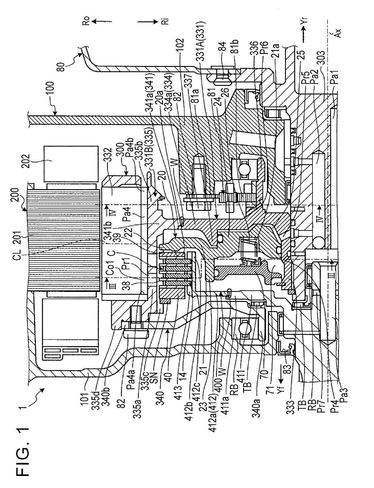
[0015]Hereinafter, an embodiment of the disclosure is disclosed. A configuration of the embodiment described below, and actions and results (effects) derived from the configuration are examples. The disclosure can be carried out with other configuration than the configuration disclosed in the following embodiment. According to the disclosure, at least one of various effects (including derivative effects) obtained from these configurations is obtained. In the drawings, a rotation center axis of a rotating electric machine 1 is denoted by Ax, a front side in the axis direction is denoted by Yf, and a rear side in the axis direction is denoted by Yr. An outer side of the radial direction is denoted by Ro, and an inner side of the radial direction is denoted by Ri. W represents a weld portion.

[0016]FIG. 1 is an exemplary and schematic sectional view of a portion of a rotating electric machine according to the embodiment on a first side with respect to the rotation center axis in the rad...


PUM


Abstract

A rotating electric machine includes a case, a stator, a first rotary member including a rotor core and a first shaft, a second rotary member including a second shaft, and a multiple disc clutch. A first oil passage and a second oil passage are provided inside the case. The first oil passage starts from an inside of the first shaft or an inside of the second shaft, passes through the multiple disc clutch from an inner side to an outer side in a radial direction with respect to a rotation center, and reaches an inner side of the rotor core in the radial direction. The second oil passage starts from the inside of the first shaft or the inside of the second shaft and reaches the inner side of the rotor core in the radial direction without passing through the multiple disc clutch.

Description

INCORPORATION BY REFERENCE[0001]The disclosure of Japanese Patent Application No. 2018-067415 filed on Mar. 30, 2018 including the specification, drawings and abstract is incorporated herein by reference in its entirety.BACKGROUND1. Technical Field[0002]The disclosure relates to a rotating electric machine.2. Description of Related Art[0003]A rotating electric machine has been known in which a multiple disc clutch is provided inward of a rotor core in a radial direction (for example, see Japanese Unexamined Patent Application Publication No. 2009-72052 (JP 2009-72052 A)). In the rotating electric machine described in JP 2009-72052 A, operating oil (oil) flowing from an inner side towards an outer side in the radial direction lubricates and cools the multiple disc clutch, and then cools the rotor core.SUMMARY[0004]However, with the foregoing conventional configuration, when a flowing amount of the operating oil necessary for cooling the rotor core is larger than a flowing amount of t...

Claims


Application Information

Patent Timeline
Patent Type & Authority Applications(United States)
IPC IPC(8): H02K9/193H02K7/108H02K1/28
CPCH02K7/108H02K1/28H02K9/193H02K7/006H02K9/197
Inventor IDEUE, SHIGEKIKATOINDA, KEITAKAMIYA, TOSHIHIKOOKISHIMA, TATSUYA
Owner TOYOTA JIDOSHA KK
Why Eureka
Try Eureka