Coil device
a coil device and coil technology, applied in the direction of transformer/inductance magnetic cores, cores/yokes, inductances, etc., can solve the problems of short circuit and possible magnetic property deterioration, and achieve the effect of preventing short circuit defects and rust generation, facilitating the formation of coil devices, and increasing the effective magnetic permeability of the element body
- Summary
- Abstract
- Description
- Claims
- Application Information
AI Technical Summary
Benefits of technology
Problems solved by technology
Method used
Image


Examples
first embodiment
[0034]As illustrated in FIG. 1A, an inductor 2 as a coil device (chip component) according to a first embodiment of the invention has an element body 4 that has a substantially rectangular parallelepiped shape (that is substantially hexahedral). It should be noted that the coil device according to the invention is not limited to the inductor 2 and may be another coil device.
[0035]The element body 4 has an upper surface 4a, a bottom surface (main surface to be a mounting surface) 4b on the side that is opposite in a Z-axis direction to the upper surface 4a, and four side surfaces 4c to 4f Although the dimensions of the element body 4 are not particularly limited, the longitudinal (X-axis) dimension of the element body 4 is preferably 1.2 to 6.5 mm, the lateral (Y-axis) dimension of the element body 4 is preferably 0.6 to 6.5 mm, and the height (Z-axis) dimension of the element body 4 is preferably 0.5 to 5.0 mm as an example.
[0036]A wire 6 is provided in the element body 4. The wire ...
second embodiment
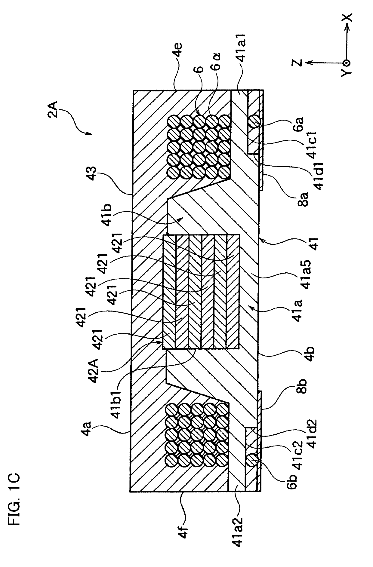
[0100]An inductor 2A according to a second embodiment illustrated in FIG. 1C has the same configuration, action, and effect as the inductor 2 according to the first embodiment except the following. Members of the inductor 2A illustrated in FIG. 1C respectively correspond to members of the inductor 2 according to the first embodiment illustrated in FIG. 1B. The corresponding members are given the same reference numerals, and description of the members is partially omitted.
[0101]As illustrated in FIG. 1C, the inductor 2A has a second core member 42A. The second core member 42A is constituted by a stacked body of a plurality of sheet-shaped (plate-shaped) magnetic metal plates 421. The thickness of the metal plate 421 is not particularly limited. Preferably, the thickness is 0.05 to 1.0 mm.
[0102]With the present embodiment, effects similar to those of the first embodiment can be obtained. In addition, the magnetic properties of the inductor 2A are improved by the magnetic metal plate 4...
third embodiment
[0104]An inductor 2B according to a third embodiment illustrated in FIG. 1D has the same configuration, action, and effect as the inductor 2 according to the first embodiment except the following. Members of the inductor 2B illustrated in FIG. 1D respectively correspond to members of the inductor 2 according to the first embodiment illustrated in FIG. 1B. The corresponding members are given the same reference numerals, and description of the members is partially omitted.
[0105]As illustrated in FIG. 1D, the inductor 2B has a second core member 42B. The second core member 42B is constituted by an assemblage of spherical bodies 422 made of spherical magnetic metal balls (such as iron balls). The number of the spherical bodies 422 accommodated in the recessed portion 41b1 is not particularly limited, and the number may be one or more. The spherical bodies 422 do not necessarily have to be neatly arranged in the recessed portion 41b1 and may be randomly disposed as illustrated in the dra...
PUM
| Property | Measurement | Unit |
|---|---|---|
| height | aaaaa | aaaaa |
| height | aaaaa | aaaaa |
| height | aaaaa | aaaaa |
Abstract
Description
Claims
Application Information
 - R&D
- Intellectual Property
- Life Sciences
- Materials
- Tech Scout
- Unparalleled Data Quality
- Higher Quality Content
- 60% Fewer Hallucinations
Browse by: Latest US Patents, China's latest patents, Technical Efficacy Thesaurus, Application Domain, Technology Topic, Popular Technical Reports.
© 2025 PatSnap. All rights reserved.Legal|Privacy policy|Modern Slavery Act Transparency Statement|Sitemap|About US| Contact US: help@patsnap.com