Fluid impermeable ultrasonic transducer
Pending Publication Date: 2019-10-03
LABCYTE
View PDF5 Cites 4 Cited by
- Summary
- Abstract
- Description
- Claims
- Application Information
AI Technical Summary
Benefits of technology
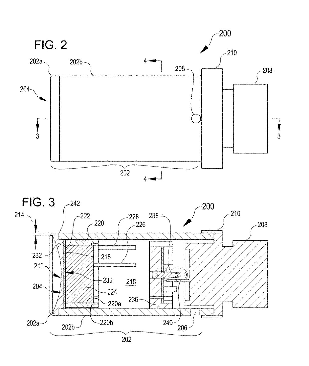
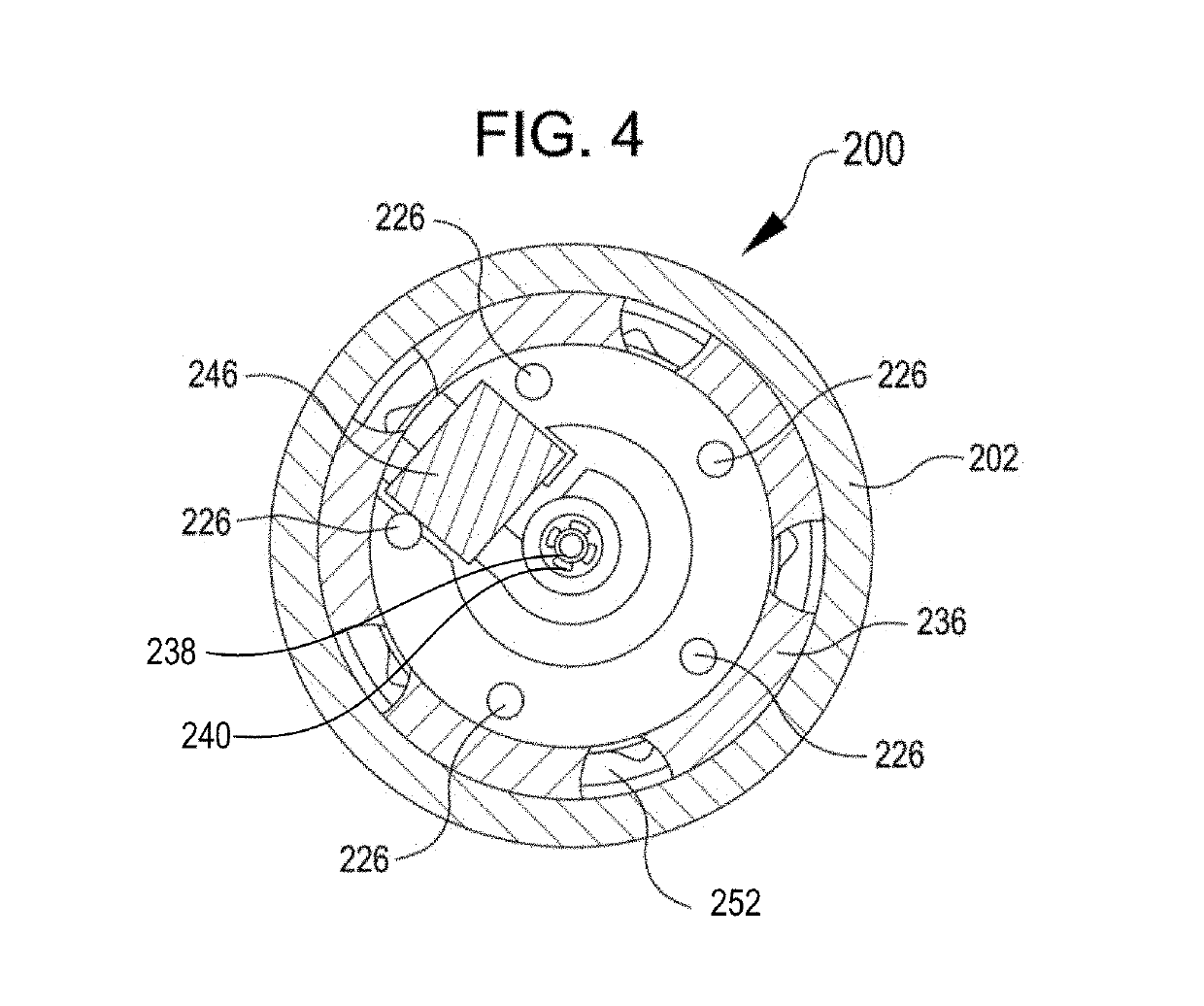
The patent is about a new type of acoustic transducer that is designed to be highly resistant to water and other fluids. The transducer is made of a casing and a transducer head, which can be made of non-absorbing solid materials like metals or ceramics. The transducer head is designed to have a similar acoustic impedance to the medium in which it is used, which helps to minimize signal loss. The transducer is also designed to be mechanically homogeneous, which ensures good beam symmetry and persistence over its lifetime. Additionally, the transducer head can include a matching layer to further reduce signal loss, which can be selected based on the properties of the medium in which it is used.
Problems solved by technology
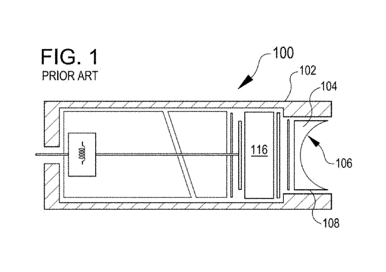
While such focusing lens materials can be formed by molding or another net-shape manufacturing method, and while generally waterproof up to a limited duration, it has been found that such materials are prone to degrade and, when exposed to water for a long duration, can tend to gradually take up water, leading to deformation, a shift in acoustic properties and ultimately to failure of the transducer.
Method used
View moreImage
Smart ImageViewing Examples
Examples
example b
[0127] The transducer of any of the preceding examples, wherein the casing comprises a metal casing connected to the metal focusing lens via a fluid impermeable joint.
example c
[0128] The transducer of Example B, wherein the fluid impermeable joint comprises a welded joint.
example d
[0129] The transducer of any of the preceding examples, wherein the casing and transducer head are connected in a fluid impermeable manner to prevent ingress of gas into the casing.
Login to View More PUM
 Abstract
A fluid impermeable transducer includes an assembly of a transducer head and a casing, and an actuator disposed in the casing rearward of the back of the transducer head and operable to transmit acoustic energy through the transducer head. The transducer head and casing define a working portion of the transducer that is fluid impermeable.
Description
CROSS-REFERENCES TO RELATED APPLICATIONS[0001]This application claims priority under 35 U.S.C. § 119(e) to U.S. Provisional Application No. 62 / 650,919 filed on Mar. 30, 2018, the entire contents of which are herein incorporated by reference for all purposes.BACKGROUND[0002]Ultrasonic transducers are used for a wide variety of applications, such as in medical imaging, for procedures in which ultrasonic energy is applied to heat or disrupt tissue within an organism, and in processes for the ejection of fluid droplets. Any or all of the above cases can require that an ultrasonic transducer be capable of focusing the acoustic energy to a small focal point. By way of example, some methods of producing fluid droplets using acoustic means include those described in U.S. Pat. No. 8,544,976 to Ellson, and in U.S. Pat. No. 6,416,164 to Stearns et al., both of which are hereby incorporated by reference for all purposes.[0003]Ultrasonic acoustic radiation may be focused by a variety of means. F...
Claims
Login to View More Application Information
Patent Timeline
 IPC IPC(8): G01N29/32H04R23/00H04R31/00G01N29/28G01N29/24
CPCG01N29/32G01N29/28G01N29/2437H04R23/00H04R31/00G01N29/2456G10K11/02G10K11/30B06B1/067B06B1/0685
Inventor HADIMIOGLU, BABURDAULTON, JAYELLSON, RICHARD N.
Owner LABCYTE
- R&D Engineer
- R&D Manager
- IP Professional
- Industry Leading Data Capabilities
- Powerful AI technology
- Patent DNA Extraction
Learn More Browse by: Latest US Patents, China's latest patents, Technical Efficacy Thesaurus, Application Domain, Technology Topic, Popular Technical Reports.
© 2024 PatSnap. All rights reserved.Legal|Privacy policy|Modern Slavery Act Transparency Statement|Sitemap|About US| Contact US: help@patsnap.com


