Distance measuring device, imaging apparatus, moving device, robot device, and recording medium
- Summary
- Abstract
- Description
- Claims
- Application Information
AI Technical Summary
Benefits of technology
Problems solved by technology
Method used
Image
Examples
first embodiment
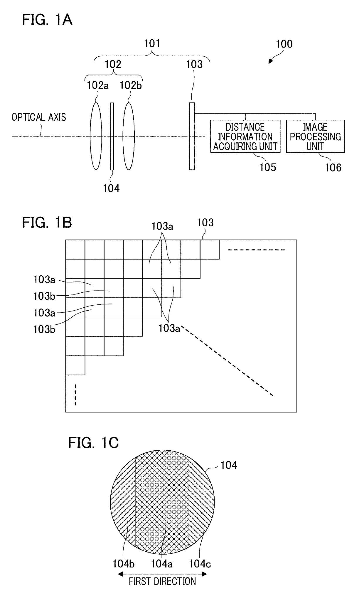
[0026]FIGS. 1A and 1B schematically illustrate a configuration of a distance measuring device according to a first embodiment of the present invention. FIG. 1A is a schematic diagram illustrating an imaging unit 101, a distance information acquiring unit 105, and an image processing unit 106, which are main components of a distance measuring device 100. The imaging unit 101 includes an imaging optical system 102 and an imaging element 103 in which many pixel portions are arranged. The imaging optical system 102 includes a plurality of lenses. For example, reflected light from an object forms an image on the imaging element 103 by lenses 102a and 102b arranged along the optical axis. The imaging optical system 102 includes an optical filter 104 at a diaphragm position between the lenses 102a and 102b.
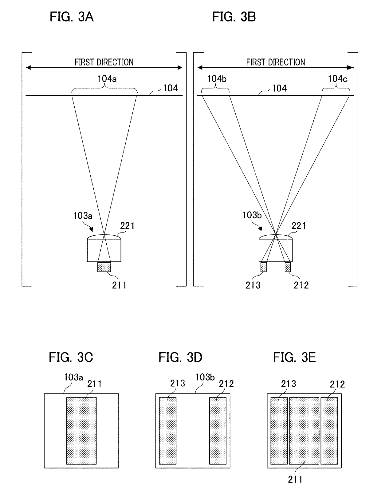
[0027]FIG. 1B is a schematic diagram illustrating the pixel arrangement of the imaging element 103. Many pixel portions of the imaging element 103 are configured by a first pixel portio...
modification 1
of the First Embodiment
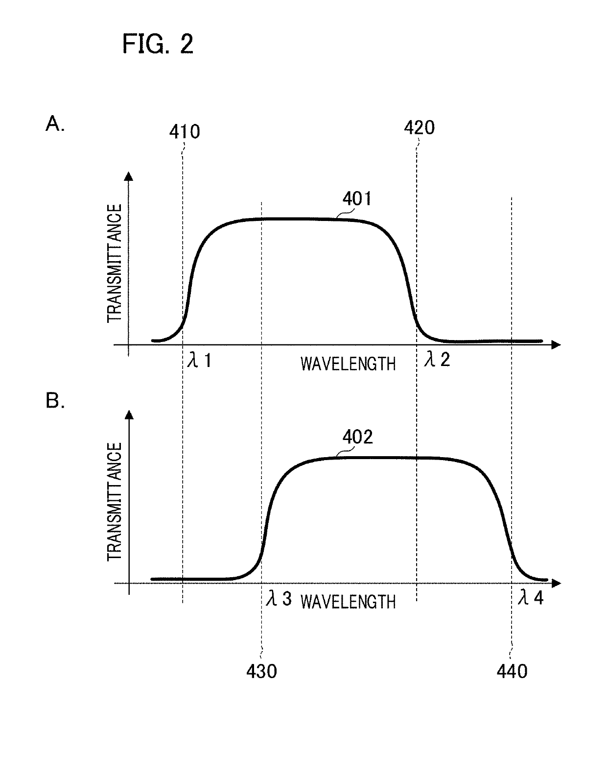
[0059]Modification 1 according to the first embodiment will be described with reference to FIGS. 8A to 8D. In the present modification, the configuration of the imaging pixel portion 103a and the distance measuring pixel portion 103b of the imaging element 103 are different from the above-described configuration. In the optical filter 104 according to the present modification, the second region 104b and the third region 104c have the spectral transmittance characteristics shown in B of FIG. 7. In the following description, the same reference numerals or symbols as those in the first embodiment are used, the detailed description thereof will be omitted, and mainly the differences will be explained. Such omission of explanation is also the same in modifications, embodiments, and the like which will be described below.
[0060]FIG. 8A illustrates the light receiving plane of an imaging pixel portion 803a included in the imaging element 103 according to the present m...
modification 2
of the First Embodiment
[0068]With reference to FIGS. 11A and 11B, a description will be given of a method for setting different wavelength bands between the imaging light flux and the distance measuring light flux in the modification 2 of the first embodiment. The imaging optical system according to the present modification has a configuration in which the optical filter 104 is removed from the imaging optical system 102.
[0069]FIG. 11A is a schematic diagram that illustrates the imaging pixel portion according to the modification and is a diagram in which an imaging pixel portion 1301a is viewed from the side. The imaging pixel portion 1301a includes the micro lens 221 and the photoelectric conversion portion 211. The imaging pixel portion 1301a includes an imaging color filter 1320a, and spectral sensitivities of blue, green, and red are applied in accordance with the spectral transmittance.
[0070]FIG. 11B is a schematic diagram that illustrates a distance measuring pixel portion ac...
PUM
 Abstract
Description
Claims
Application Information
 - R&D
- Intellectual Property
- Life Sciences
- Materials
- Tech Scout
- Unparalleled Data Quality
- Higher Quality Content
- 60% Fewer Hallucinations
Browse by: Latest US Patents, China's latest patents, Technical Efficacy Thesaurus, Application Domain, Technology Topic, Popular Technical Reports.
© 2025 PatSnap. All rights reserved.Legal|Privacy policy|Modern Slavery Act Transparency Statement|Sitemap|About US| Contact US: help@patsnap.com


