
Honeycomb filter

a honeycomb filter and filter body technology, applied in physical/chemical process catalysts, metal/metal-oxide/metal-hydroxide catalysts, separation processes, etc., can solve the problems of deteriorating trapping performance and deteriorating trapping performance of honeycomb filters, so as to improve purification performance, increase the trapping performance, and increase the effect of trapping performan

Active Publication Date: 2019-10-03
NGK INSULATORS LTD +1
View PDF0 Cites 0 Cited by
  • Summary
  • Abstract
  • Description
  • Claims
  • Application Information

AI Technical Summary

Benefits of technology

The present invention provides a honeycomb filter that improves performance in trapping and purifying harmful components from exhaust gas. The filter has a catalyst layer containing a platinum group element on the side of the outflow end face of the honeycomb structure. This layer increases the trapping performance of the filter by trapping PM and also enhances the purification performance by reducing harmful components in the exhaust gas. The platinum group element-containing catalyst layer prevents the small pores of the partition walls on the side of the outflow end face of the honeycomb structure from being closed by PM, which improves the filter's trapping performance. Additionally, the contact between the platinum group element-containing catalyst layer and the exhaust gas is increased, which further enhances the purification performance. The catalyst layer also helps to suppress the increase in pressure loss of the filter during use.

Problems solved by technology

Conventionally, the honeycomb filter using the honeycomb structure having the high porosity has a problem in that the trapping performance for trapping the PM deteriorates when the PGM catalyst is loaded.
That is, the exhaust gas becomes difficult to flow in the small pores which contribute to the improvement of the trapping performance, and as a result the trapping performance of the honeycomb filter deteriorates.

Method used


Image

  • Honeycomb filter
  • Honeycomb filter
  • Honeycomb filter

Examples


first embodiment

(1) Honeycomb Filter (First Embodiment)

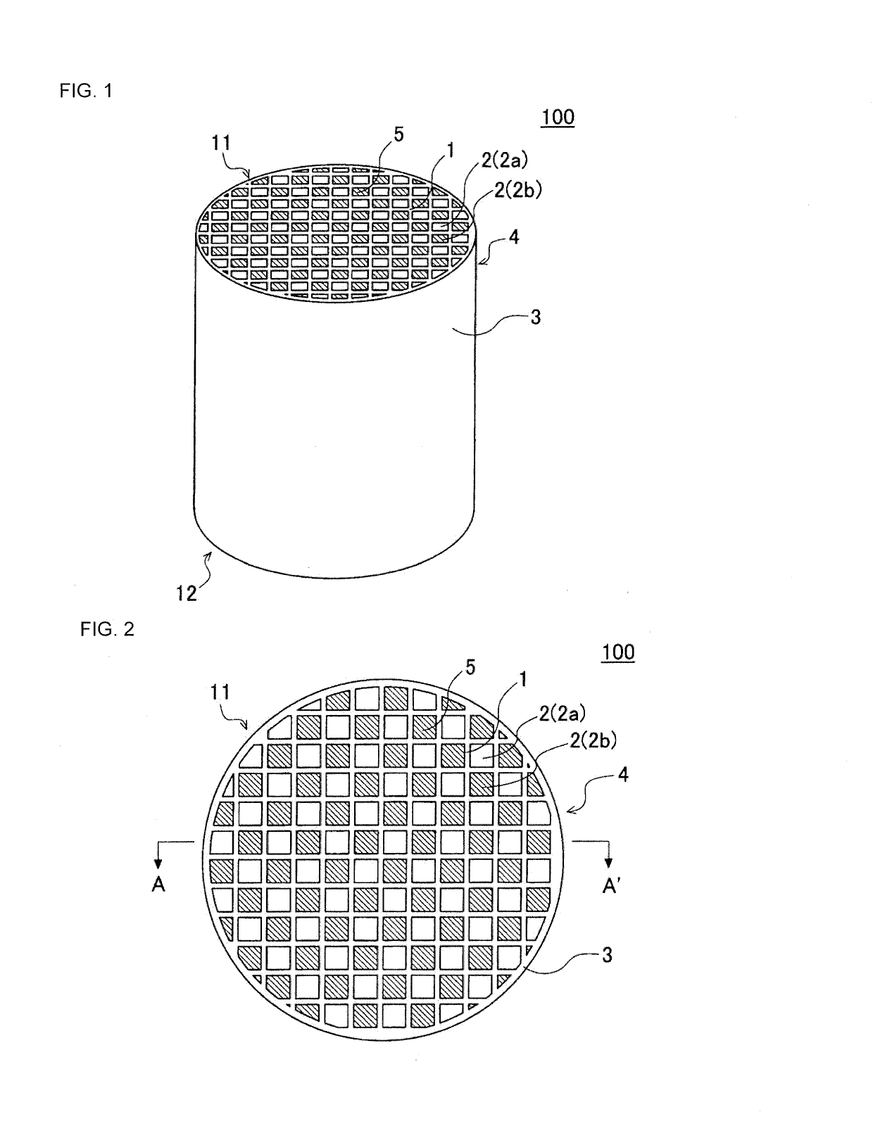
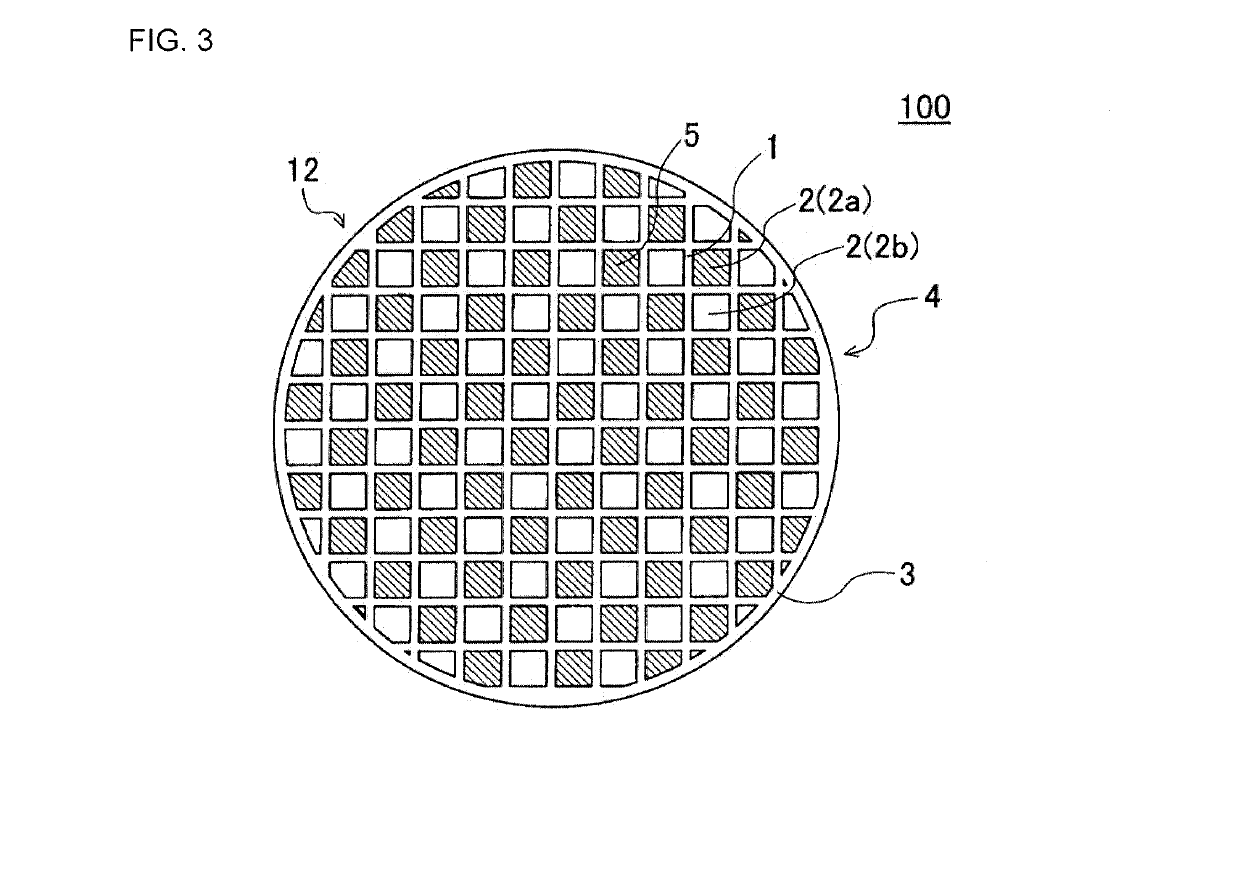
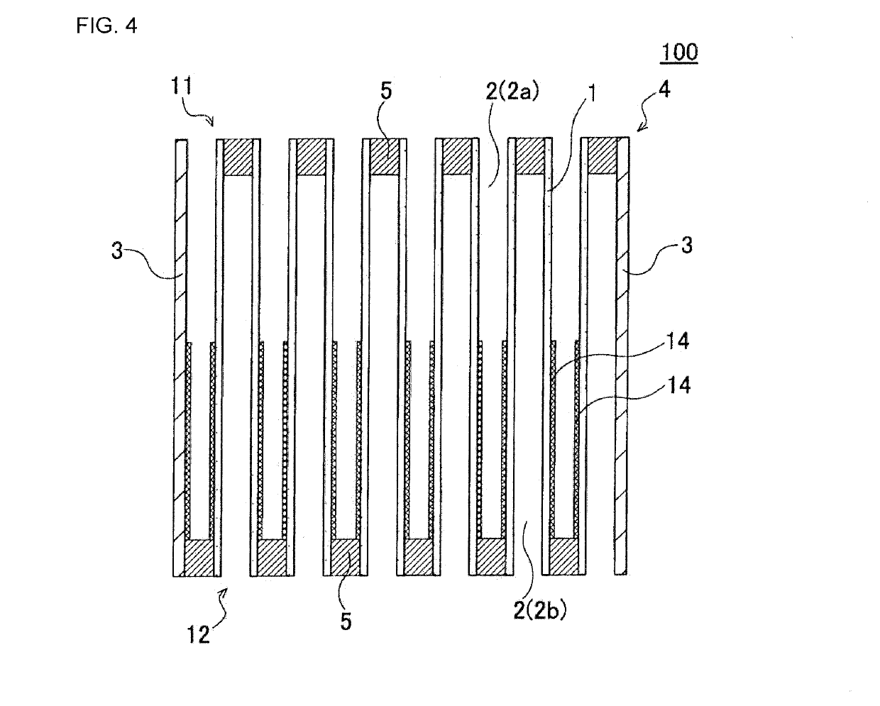
[0042]A first embodiment of a honeycomb filter of the present invention is a honeycomb filter 100 as shown in FIGS. 1 to 4. Here, FIG. 1 is a perspective view schematically showing the first embodiment of the honeycomb filter of the present invention. FIG. 2 is a plane view of a side of an inflow end face of the honeycomb filter shown in FIG. 1. FIG. 3 is a plane view of a side of an outflow end face of the honeycomb filter shown in FIG. 1. FIG. 4 is a cross-sectional view schematically showing a cross section taken along line A-A′ of FIG. 2.

[0043]As shown in FIGS. 1 to 4, the honeycomb filter 100 according to the present embodiment includes a honeycomb structure 4 and plugging portions 5. The honeycomb structure 4 has porous partition walls 1 disposed so as to surround a plurality of cells 2 as through channels of fluid extending from an inflow end face 11 to an outflow end face 12. The honeycomb structure 4 shown in FIGS. 1 to 4 is formed in ...

second embodiment

(2) Honeycomb Filter (Second Embodiment)

[0069]Next, a second embodiment of a honeycomb filter according to the present invention will be described below. The second embodiment of a honeycomb filter according to the present invention is a honeycomb filter 200 as shown in FIGS. 5 and 6. Here, FIG. 5 is a plane view of a side of an inflow end face schematically showing the second embodiment of the honeycomb filter according to the present invention. FIG. 6 is a cross-sectional view schematically showing a cross section taken along line B-B′ of FIG. 5.

[0070]As shown in FIGS. 5 and 6, the honeycomb filter 200 according to the present embodiment is a honeycomb filter 200 which includes a honeycomb structure 24 and plugging portions 25. The honeycomb structure 24 has porous partition walls 21 disposed so as to surround a plurality of cells 22 as through channels of fluid extending from an inflow end face 31 to an outflow end face 32. A circumferential side surface of the honeycomb structur...

third embodiment

(3) Honeycomb Filter (Third Embodiment)

[0077]Next, a third embodiment of a honeycomb filter according to the present invention will be described below. The third embodiment of a honeycomb filter according to the present invention is a honeycomb filter 300 as shown in FIGS. 7 to 9. Here, FIG. 7 is a perspective view schematically showing the third embodiment of the honeycomb filter according to the present invention. FIG. 8 is a plane view of a side of an inflow end face of the honeycomb filter shown in FIG. 7. FIG. 9 is a cross-sectional view schematically showing a cross section taken along line C-C′ of FIG. 8.

[0078]As shown in FIGS. 7 to 9, the honeycomb filter 300 according to the present embodiment is a honeycomb filter 300 which includes a honeycomb structure 44 and plugging portions 45. The honeycomb structure 44 has porous partition walls 41 disposed so as to surround a plurality of cells 42 as through channels of fluid extending from an inflow end face 51 to an outflow end f...


PUM

PropertyMeasurementUnit
porosityaaaaaaaaaa
thicknessaaaaaaaaaa
porosityaaaaaaaaaa

Abstract

A honeycomb filter, including:a honeycomb structure,wherein the honeycomb structure includes a platinum group element-containing catalyst layer,the platinum group element-containing catalyst layer is disposed only on a side of an inner surface of the partition walls surrounding the inflow cells, andthe platinum group element-containing catalyst layer is disposed in a range of at least up to 40% with respect to an overall length of the cells starting from the outflow end face and is not disposed in a range of at least up to 30% with respect to the overall length of the cells starting from the inflow end face, in an extending direction of the cells of the honeycomb structure.

Description

[0001]The present application is an application based on JP-2018-066811 filed on Mar. 30, 2018 with Japan Patent Office, the entire contents of which are incorporated herein by reference.BACKGROUND OF THE INVENTIONField of the Invention[0002]The present invention relates to a honeycomb filter. More particularly, the present invention relates to a honeycomb filter which is excellent in trapping performance for trapping particulate matter contained in exhaust gas and excellent in purification performance for purifying harmful components contained in the exhaust gas.Description of the Related Art[0003]In recent years, regulations on removal of particulate matter contained in exhaust gas emitted from a gasoline engine are getting stricter around the world, and a honeycomb filter having a honeycomb structure has been used as a filter for removing particulate matter. Hereinafter, the particulate matter may be referred to as “PM”. The PM is an abbreviation for “the particulate matter”.[000...

Claims


Application Information

Patent Timeline
Patent Type & Authority Applications(United States)
IPC IPC(8): F01N3/022B01J35/04B01J23/42
CPCB29C48/11F01N3/0222B01J23/42B01J35/04B01D46/0002B01D46/2418F01N3/022B01D46/0027F01N2330/06B29C48/022B29C48/345F01N2510/0682F01N3/035B01J35/56
Inventor YOSHIOKA, FUMIHIKOHATEKAYAMA, YOSHIAKIMASUMITSU, NORITAKA
Owner NGK INSULATORS LTD
Learn More