
Control station for electrical installation

a control station and electrical installation technology, applied in the direction of electric switches, basic electric elements, electric apparatus, etc., can solve the problems of requiring a greater space, too high thickness or height of the box, and considering the thickness of the box, so as to reduce the maximum transverse dimension of the box

Pending Publication Date: 2019-09-26
PIZZATO ELETTRICA
View PDF0 Cites 0 Cited by
  • Summary
  • Abstract
  • Description
  • Claims
  • Application Information

AI Technical Summary

Benefits of technology

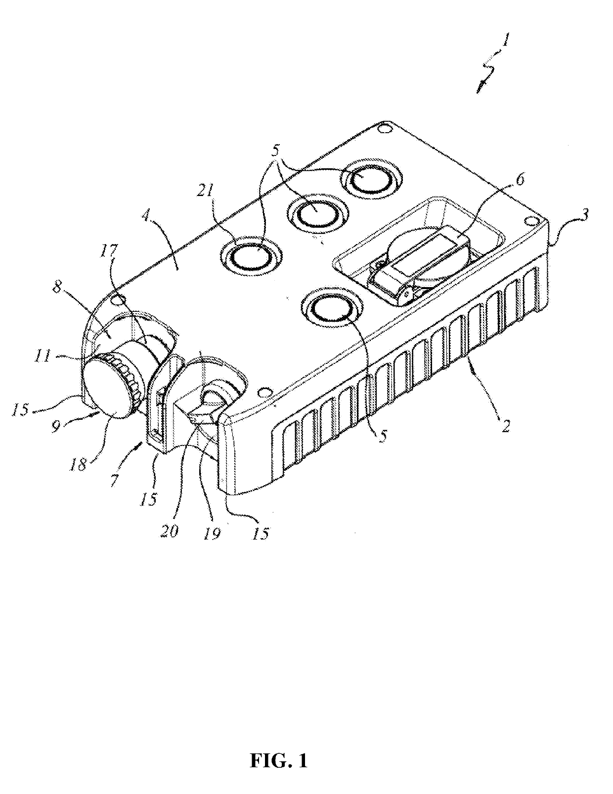
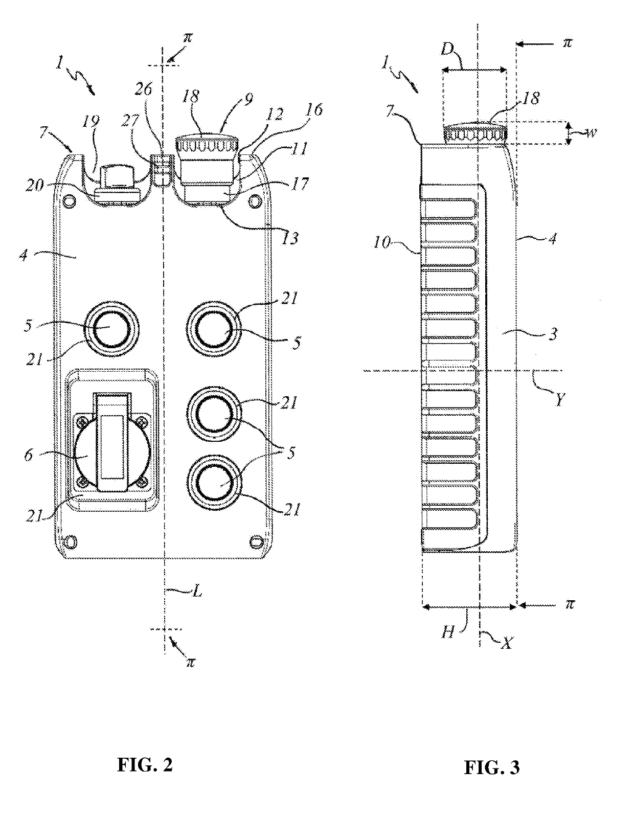
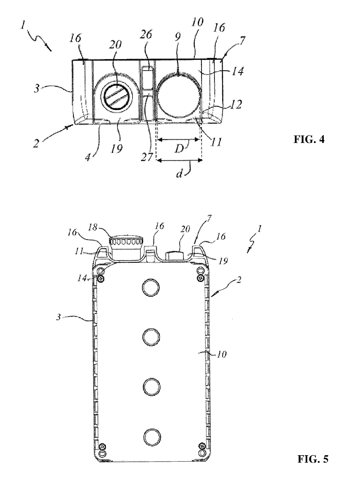
The patent text describes a control station for electrical installation that has high protection against accidental operations. The control station has multiple buttons that are associated with contact units with movable electrical contacts. The contact units can be easily removed or inserted for higher configurability and easier maintenance. Moreover, the design of the mushroom button reduces the size of the control station, making it easier to install in limited space conditions. The mushroom button does not protrude from the front of the box, which makes it thinner and more compact than common boxes for control stations.

Problems solved by technology

A problem common to all these control stations is represented by the fact that they have considerable dimensions in thickness.
This condition may represent a limitation especially in cases wherein the control stations are designed to be installed inside the pit of elevators, hoists and similar transport systems, for the control of the system during inspection and maintenance.
In these cases, in fact, a too high thickness or height of the box may require a greater need for space, not always available.
This drawback is even more relevant in those cases in which the control station is provided with a mushroom-type emergency button, which is notoriously the bulkiest control.
A further limitation of most of the control stations on the market is represented by the fact that the various commands are connected to the respective electrical contacts in a fixed and non-configurable manner, further limiting the flexibility of use of the control station.

Method used


Image

  • Control station for electrical installation
  • Control station for electrical installation
  • Control station for electrical installation

Examples


Embodiment Construction

[0036]With reference to the attached figures, a preferred but not exclusive configuration of a control station for electrical systems is shown, particularly designed to be connected to a movement or transportation system for people and / or things.

[0037]According to a preferred but not exclusive application, the control station will be designed to be installed in the pit of an elevator or hoist.

[0038]As visible from FIG. 1, the control station, indicated globally by 1, will comprise a protection box 2 having a side wall 3 with a front face 4 having a development plane π and defining a longitudinal development axis L parallel to the same development plan π.

[0039]Inside the box 2 there is a plurality of fixed and / or movable electrical contacts, not visible from the figures but which may be of a known type, connectable to one or more power and / or service circuits of the electrical system, not shown, for opening and / or closing thereof.

[0040]On the front face 4 of the box 2 a plurality of ...


PUM


Abstract

A control station for electrical installation comprises a protection box (2) having a side wall (3) with a front face (4) defining a development plane (π), a plurality of controls (5, 9, 20) anchored to the protection box (2), at least one of the controls being a mushroom emergency push button (9), movable electrical contacts associated with respective controls (5, 9, 20) to be connected to one or more circuits of the electrical installation for the opening / closing thereof. Each control (5, 9, 20) is associated with one or more contact units (22) having movable electrical contacts arranged in the protection box (2) The emergency push button (9) is housed in a seat (8) formed on a side face (7) of the side wall (3) perpendicular to the development plane (π) and is anchored to one or more contact units (22) removably housed in the protection box (2).

Description

TECHNICAL FIELD[0001]The present invention finds application in the field of devices for the control of electrical systems and has for object a control station for electrical plants, in particular for transport or movement systems such as elevators, hoists and similar.STATE OF THE ART[0002]The known control stations or pushbuttons for the control of electrical systems, such as elevators, hoists and similar handling and transport systems, generally comprise a box for housing the contact units to be connected to the various power and service circuits.[0003]Each contact unit is associated with a respective external control, such as push-buttons, switches, selectors, mushroom-type emergency pushbuttons and the like, according to the functions provided for the control station.[0004]Typically, the controls are housed in corresponding holes all made on the same face of the box, generally the wider front face.[0005]An example of a similar control station is shown in EP2447972, in the name o...

Claims


Application Information

Patent Timeline
Patent Type & Authority Applications(United States)
IPC IPC(8): H01H3/02H01H9/02H01H13/14H01H13/04
CPCH01H9/0214H01H13/04H01H2205/002H01H13/14H01H3/022H01H13/70
Inventor PIZZATO, MARCO
Owner PIZZATO ELETTRICA
Learn More