
Actuator and optical scanning device

a scanning device and actuator technology, applied in the field of actuators and optical scanning devices, can solve the problems of reducing the quality of images formed, affecting the operation of the device,

Active Publication Date: 2019-09-19
MITSUMI ELECTRIC CO LTD
View PDF0 Cites 1 Cited by
  • Summary
  • Abstract
  • Description
  • Claims
  • Application Information

AI Technical Summary

Benefits of technology

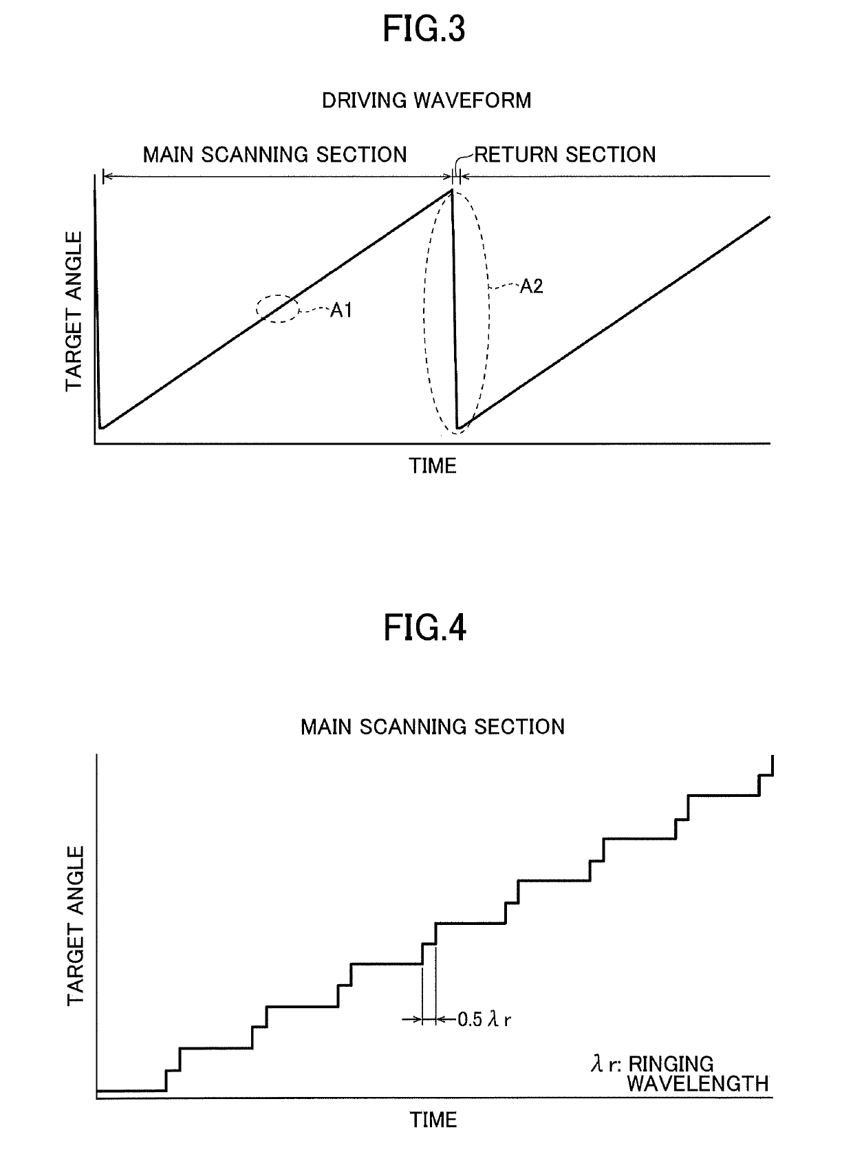
The patent text describes a way to reduce ringing in a driving waveform by using half sine waves with a specific wavelength. This configuration helps to create a more stable waveform and minimize the ringing effect.

Problems solved by technology

The ringing may reduce the quality of images formed by scanning light with the optical scanning device.
However, when a method where a frequency filter is applied to the entire driving waveform is used for a sawtooth waveform with step-like main-scanning sections, the steps may become blunt and necessary straight sections may not be obtained.
Also, although a filtering method is effective for a continuously-repeated sawtooth waveform, the method cannot achieve an appropriate ringing suppression effect in a case where the frequency of the sawtooth waveform fluctuates or a case where a wait time occurs irregularly between sawtooth waveforms.

Method used


Image

  • Actuator and optical scanning device
  • Actuator and optical scanning device
  • Actuator and optical scanning device

Examples


embodiment

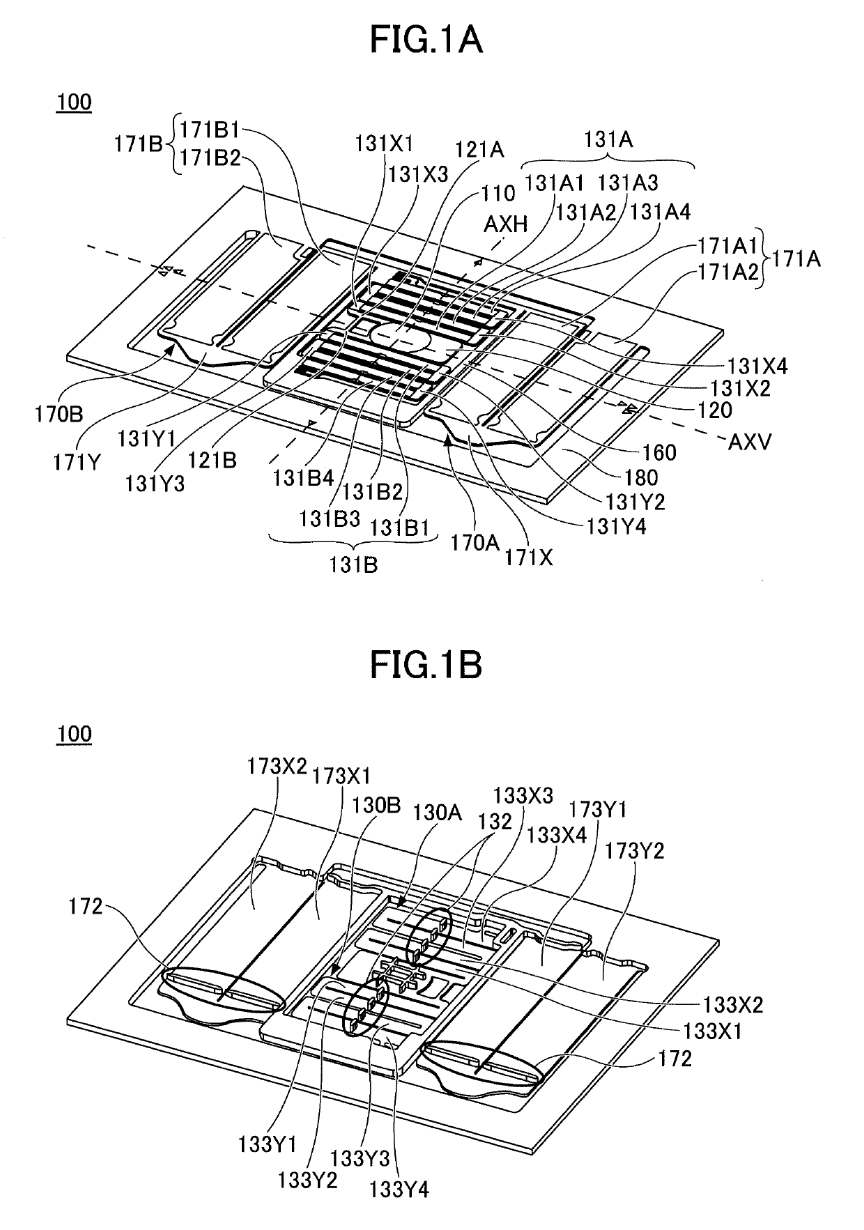
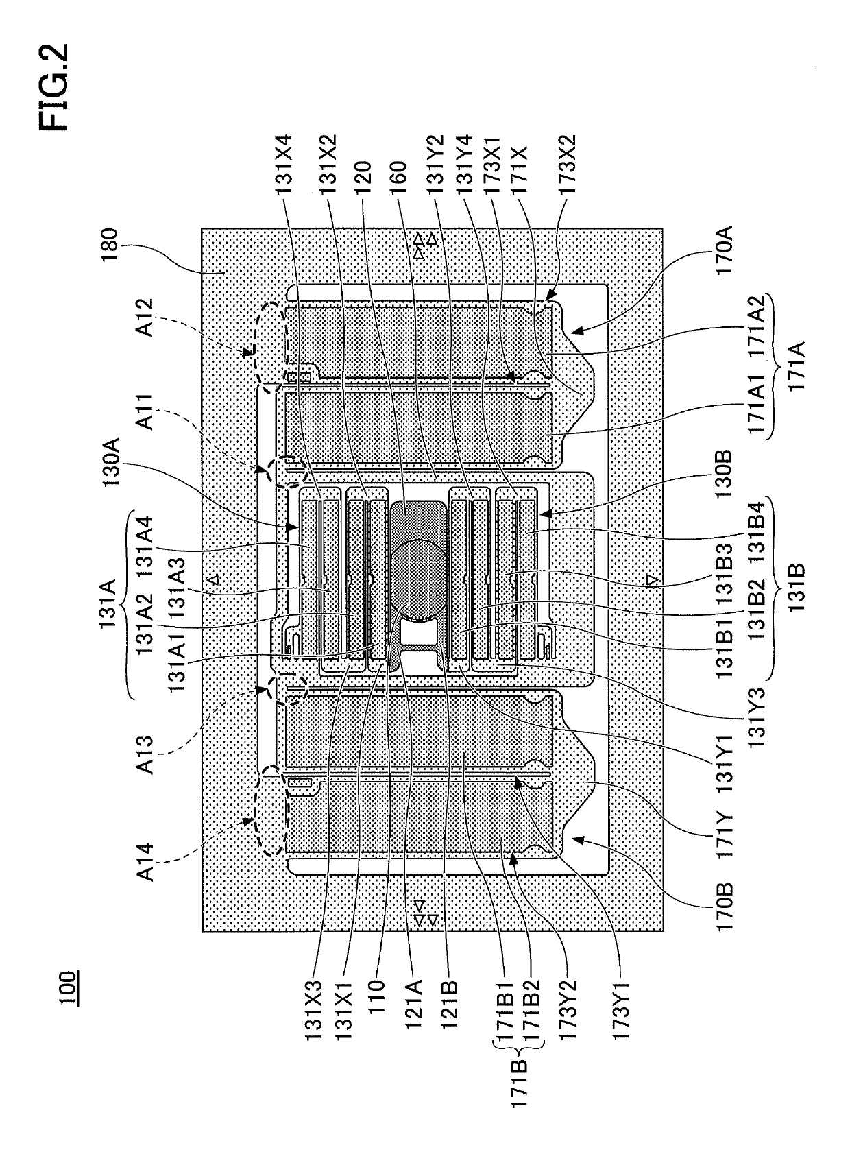
[0030]FIG. 1A is a top perspective view of an optical scanner 100 of an optical scanning device according to an embodiment. FIG. 1B is a bottom perspective view of the optical scanner 100 of FIG. 1A. FIG. 2 is a top plan view of the optical scanner 100 of FIG. 1A. The optical scanner 100 may be housed in a ceramic package including a package body and a package cover.

[0031]The optical scanner 100 scans an incoming laser beam emitted by a light source by causing a mirror 110 to rotate (or oscillate). The optical scanner 100 is, for example, a MEMS mirror where the mirror 110 is driven by driving sources such as piezoelectric elements. The mirror 110 of the optical scanner 100 reflects an incoming laser beam and scans the reflected laser beam two-dimensionally.

[0032]As illustrated in FIGS. 1A, 1B, and 2, the optical scanner 100 includes the mirror 110, a mirror support 120, coupling beams 121A and 121B, horizontal driving beams 130A and 130B, a movable frame 160, vertical driving beams...


PUM


Abstract

An actuator includes a beam that supports an object to be driven, and a driving source that receives a driving signal and causes the object to rotate around a predetermined axis. The driving signal includes a sawtooth driving waveform, and a differential waveform of a falling section of the sawtooth driving waveform is formed of half sign waves having a wavelength that is a non-integral multiple of a ringing wavelength.

Description

CROSS-REFERENCE TO RELATED APPLICATION[0001]The present application is based upon and claims priority to Japanese Patent Application No. 2018-048094, filed on Mar. 15, 2018, the entire contents of which are incorporated herein by reference.BACKGROUND OF THE INVENTION1. Field of the Invention[0002]An aspect of this disclosure relates to an actuator and an optical scanning device.2. Description of the Related Art[0003]There is a known optical scanning device where a mirror is rotated around a rotational axis to scan light reflected by the mirror by using an actuator including, as a driving source, a piezoelectric element that includes an upper electrode formed on the upper surface of a piezoelectric thin film and a lower electrode formed on the lower surface of the piezoelectric thin film. The actuator also includes an upper wire connected to the upper electrode and a lower wire connected to the lower electrode that are used to apply a voltage to the piezoelectric thin film (see, for ...

Claims


Application Information

Patent Timeline
IPC IPC(8): G02B26/08G02B26/10H02N2/04H02N2/06
CPCG02B26/0858H02N2/046G02B26/10H02N2/06G02B26/105G02B26/101H10N30/802H10N30/2044
Inventor YAMADA, KENSUKE
Owner MITSUMI ELECTRIC CO LTD
Learn More