
Valve actuator, valve, and machine consisting thereof

a valve actuator and valve body technology, applied in the direction of valve details, packaging, liquid bottling, etc., can solve the problems of natural unpracticalness and actuator heat up quickly, and achieve the effect of facilitating core switching

Active Publication Date: 2019-09-19
SERAC GROUP
View PDF9 Cites 2 Cited by
  • Summary
  • Abstract
  • Description
  • Claims
  • Application Information

AI Technical Summary

Benefits of technology

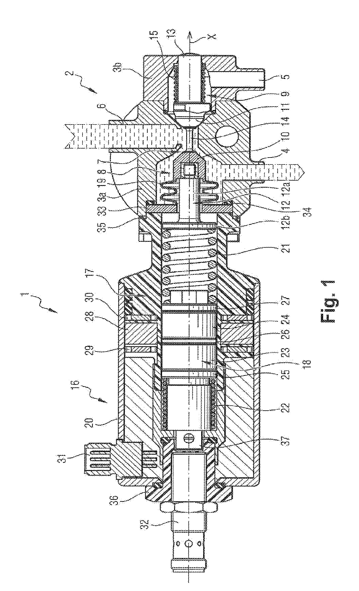
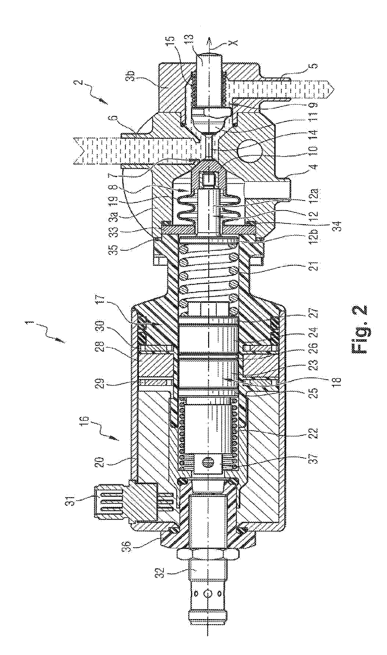
The invention is a valve actuator that can put an admission channel of the valve into communication with at least one outlet of the valve by sliding a plug along a given axis between two end positions. The moving equipment includes a core that is constrained to move in translation with the plug along the given axis. This design prevents the actuator from overheating, and the coil is powered only for the time required to switch the core (and thus the plug) from one position to another. The elastically deformable elements facilitate switching the core (and thus the plug) over from one position to another position.

Problems solved by technology

These valves are generally associated with pneumatic valve actuators, which is incompatible with aseptic environments complying with very strict hygiene and security standards.
Under such circumstances, in order to be able to use valves of this type in aseptic environments, it would be appropriate to arrange the actuator outside the aseptic environments in question, which is naturally not very practical.
Nevertheless, the actuator then tends to heat up quickly in operation, which is particularly problematic given that the actuator is sometimes subjected to temperature constraints that are already severe.

Method used


Image

  • Valve actuator, valve, and machine consisting thereof
  • Valve actuator, valve, and machine consisting thereof
  • Valve actuator, valve, and machine consisting thereof

Examples


Embodiment Construction

[0031]With reference to the various figures, the valve actuator, given overall reference 1, in a particular embodiment of the invention is associated with a valve, given overall reference 2. In this example, the valve 2 has a valve body 3a in which there are provided two outlets 4 and 5 and an admission channel 6 connected to the two outlets 4 and 5, said valve body 3a being closed at a second of its ends by a cover 3b of the valve 2, the actuator 1 being mounted on the valve 2 at a first end of the valve body 3a. In this example, the valve 2 is thus a three-port valve.

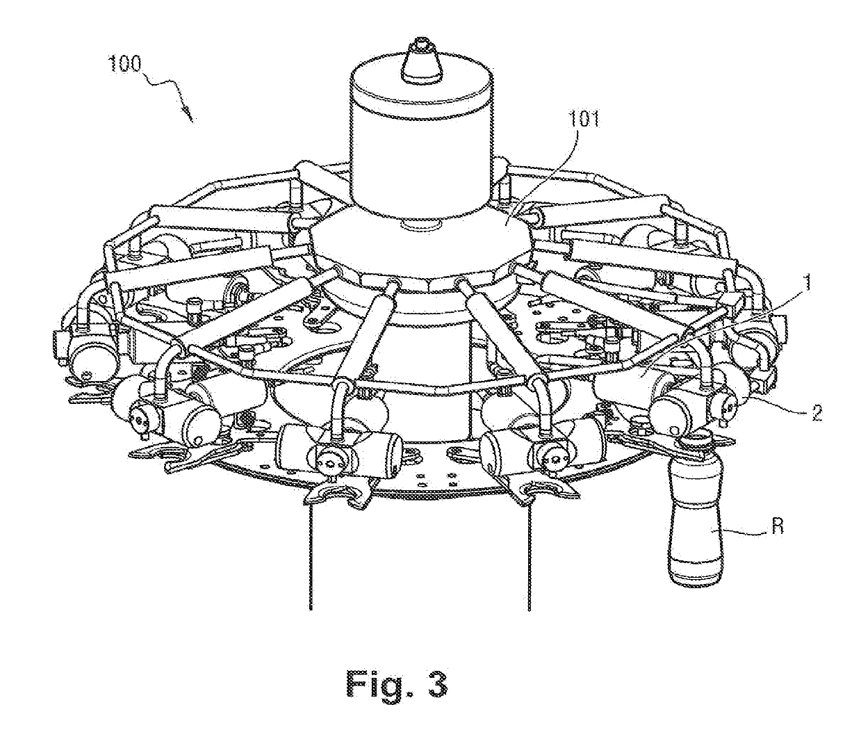
[0032]Said valve 2 and said actuator 1 are mounted together on a carousel 101 of a machine, given overall reference 100, for example a machine for transporting containers R (such as a machine for decontaminating containers, a machine for filling containers, . . . ). In the present example, the carousel 101 has a plurality of valves and valve actuators that are identical and that are in accordance with the particular e...


PUM


Abstract

A valve actuator includes moving equipment arranged to cause a plug of said equipment to slide along a given axis between two end positions. The moving equipment includes a core constrained to move in translation with the plug along the given axis. The actuator also includes a coil lying between two rings of ferromagnetic material, all three of which are secured to a frame of the actuator so as to surround the core, which itself carries two magnets mounted in opposition on the core level with the coil, a ring of ferromagnetic material lying between the two magnets that also lie between two other rings of ferromagnetic material. A valve and a machine may be fitted with such an actuator.

Description

[0001]The invention relates to a valve actuator.[0002]The invention also relates to a valve equipped with such an actuator.[0003]The invention also relates to a machine including such a valve and such an actuator, by way of example and in non-limiting manner, a machine such as a machine for transporting containers.TECHNOLOGICAL BACKGROUND OF THE INVENTION[0004]In order to enable an inlet to be associated with two different outlets, it is known to make use of three-port valves.[0005]These valves are generally associated with pneumatic valve actuators, which is incompatible with aseptic environments complying with very strict hygiene and security standards. Under such circumstances, in order to be able to use valves of this type in aseptic environments, it would be appropriate to arrange the actuator outside the aseptic environments in question, which is naturally not very practical.[0006]In order to mitigate that drawback, proposals have been made to have recourse to electrical valve...

Claims


Application Information

Patent Timeline
IPC IPC(8): F16K31/08
CPCF16K31/08B67C3/28F16K31/0634F16K31/0641F16K31/082F16K37/0041Y10T137/86895
Inventor GRUSON, BERTRAND
Owner SERAC GROUP
Learn More