Component for timepiece, movement, and timepiece
- Summary
- Abstract
- Description
- Claims
- Application Information
AI Technical Summary
Benefits of technology
Problems solved by technology
Method used
Image

Examples
first embodiment
[0029]A movement and a timepiece including a component for a timepiece according to a first embodiment of the present invention will be described with reference to FIG. 1.
[0030]In general, a mechanical body including a driving part of the timepiece is called a “movement”. A state where a dial and a needle are attached to the movement, put in a timepiece case, and made into a finished product is called a “complete” of the timepiece.
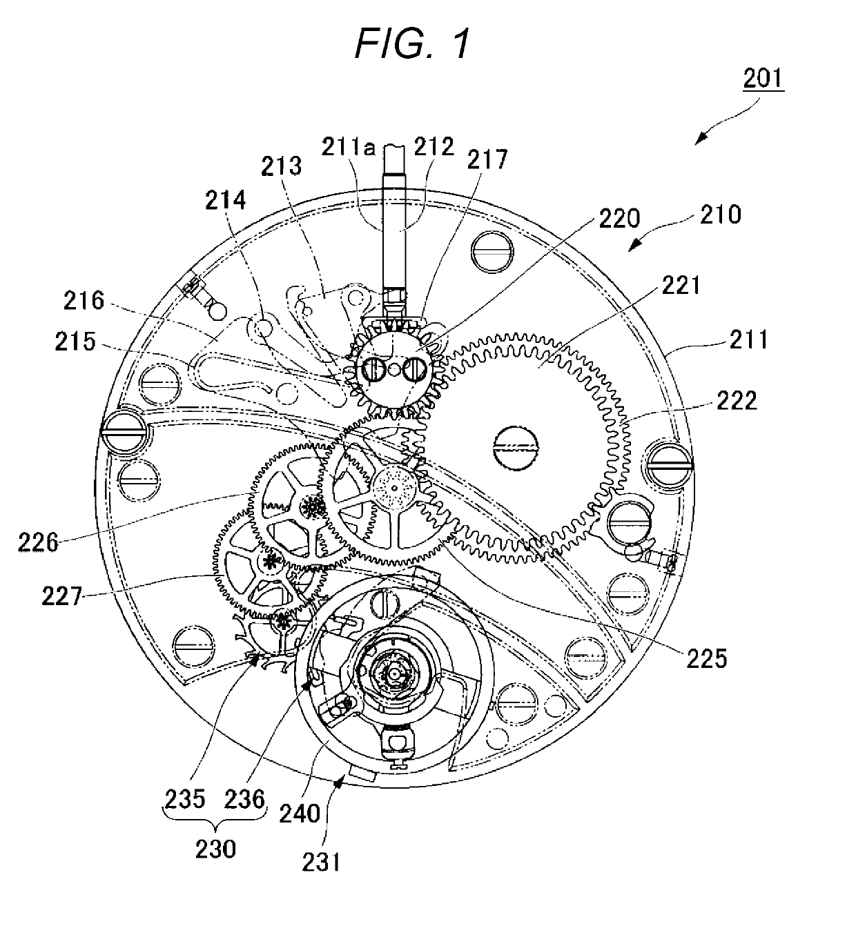
[0031]FIG. 1 is a plan view of a front side of the movement.
[0032]As illustrated in FIG. 1, a mechanical timepiece 201 is configured with a movement 210 and a casing (not illustrated) that houses the movement 210.
[0033]The movement 210 has a main plate 211 that configures a board. A dial (not illustrated) is arranged on a rear side of the main plate 211. In addition, a gear train incorporated in the front side of the movement 210 is referred to as a front wheel train and the gear train incorporated in the rear side of the movement 210 is referred to as a r...
second embodiment
[0099]The component for a timepiece according to a second embodiment of the present invention will be described with reference to FIG. 4.
[0100]FIG. 4 is a side view illustrating a wheel 60 which is the component for a timepiece according to the second embodiment of the present invention.
[0101]As illustrated in FIG. 4, the wheel 60 includes a shaft portion 51 and a wheel portion 52 fixed to the shaft portion 51.
[0102]A first end portion 53 (first tenon portion) and a second end portion 54 (second tenon portion) of the shaft portion 51 are rotatably supported by a bearing (not illustrated). There is a possibility that the outer circumferential surfaces of the first end portion 53 and the second end portion 54 slide against the inner circumferential surface of the bearing. There is a possibility that the outer circumferential surface of an intermediate portion 55 (intermediate portion in the longitudinal direction) of the shaft portion 51 slides against the inner circumferential surfac...
third embodiment
[0114]The component for a timepiece according to a third embodiment of the present invention will be described with reference to FIG. 5.
[0115]FIG. 5 is a perspective view and a sectional view illustrating a hole stone 75 which is the component for a timepiece according to the third embodiment of the present invention.
[0116]As illustrated in FIG. 5, the hole stone 75 has a circular shape, for example, in a planar view. The hole stone 75 has a through-hole 74. The hole stone 75 is formed of, for example, ruby or the like.
[0117]The through-hole 74 is formed to penetrate the hole stone 75 in the thickness direction. The through-hole 74 is formed, for example, at the center of the hole stone 75 in a planar view. The through-hole 74 has a circular shape, for example, in a planar view. In the through-hole 74, for example, a tenon portion of the shaft body is inserted. As the shaft body, for example, the same configuration as the shaft portion 51 of the wheel 60 illustrated in FIG. 4 can be...
PUM
 Abstract
Description
Claims
Application Information
 - R&D
- Intellectual Property
- Life Sciences
- Materials
- Tech Scout
- Unparalleled Data Quality
- Higher Quality Content
- 60% Fewer Hallucinations
Browse by: Latest US Patents, China's latest patents, Technical Efficacy Thesaurus, Application Domain, Technology Topic, Popular Technical Reports.
© 2025 PatSnap. All rights reserved.Legal|Privacy policy|Modern Slavery Act Transparency Statement|Sitemap|About US| Contact US: help@patsnap.com