Corner cabinet fitting for the gearwheel-controlled movable mounting of a shelf in a corner cabinet

Active Publication Date: 2019-09-12
VAUTH SAGEL HLDG
View PDF16 Cites 1 Cited by
  • Summary
  • Abstract
  • Description
  • Claims
  • Application Information

AI Technical Summary

Benefits of technology

The present invention is about a corner cabinet with a fitting system. The fitting system includes a bearing pedestal, a supporting arm, and a shelf carrier. The shelf carrier is pivotable in a second pivoting movement about a second vertical pivot axis, which is coupled to the first pivoting movement of the supporting arm. This coupling mechanism uses two rolling elements, one of which is coupled to the bearing pedestal and the other which is coupled to the shelf carrier. The technical effect of this invention is to provide a fitting system for a corner cabinet that allows for smooth pivoting movements and secure mounting of the shelf carrier to the supporting arm.

Problems solved by technology

This is unfavorable with regard to the accessibility of the parts of the shelf which cannot be completely pulled out of the corner cabinet.
The known corner cabinet fitting has a very complex construction, and, due to the basically present degrees of freedom of movement of the shelf with regard to the supporting arms, it is low in stability of movement guiding.
As compared to the base area of the respective corner cabinet, the possible size of the shelf is, however, comparatively small even with this known corner cabinet fitting.
Further, due to the small distance between the spatially fixed vertical pivot axes of the supporting arm and of the control lever, high forces on the control lever and its bearings come about.

Method used


Image

  • Corner cabinet fitting for the gearwheel-controlled movable mounting of a shelf in a corner cabinet
  • Corner cabinet fitting for the gearwheel-controlled movable mounting of a shelf in a corner cabinet
  • Corner cabinet fitting for the gearwheel-controlled movable mounting of a shelf in a corner cabinet

Examples


Embodiment Construction

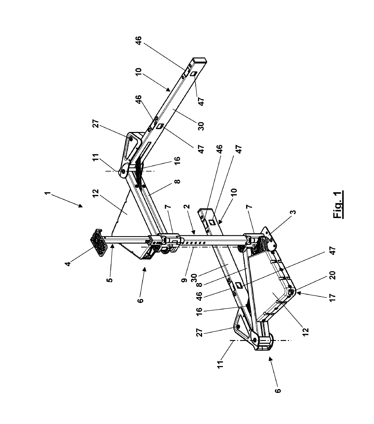
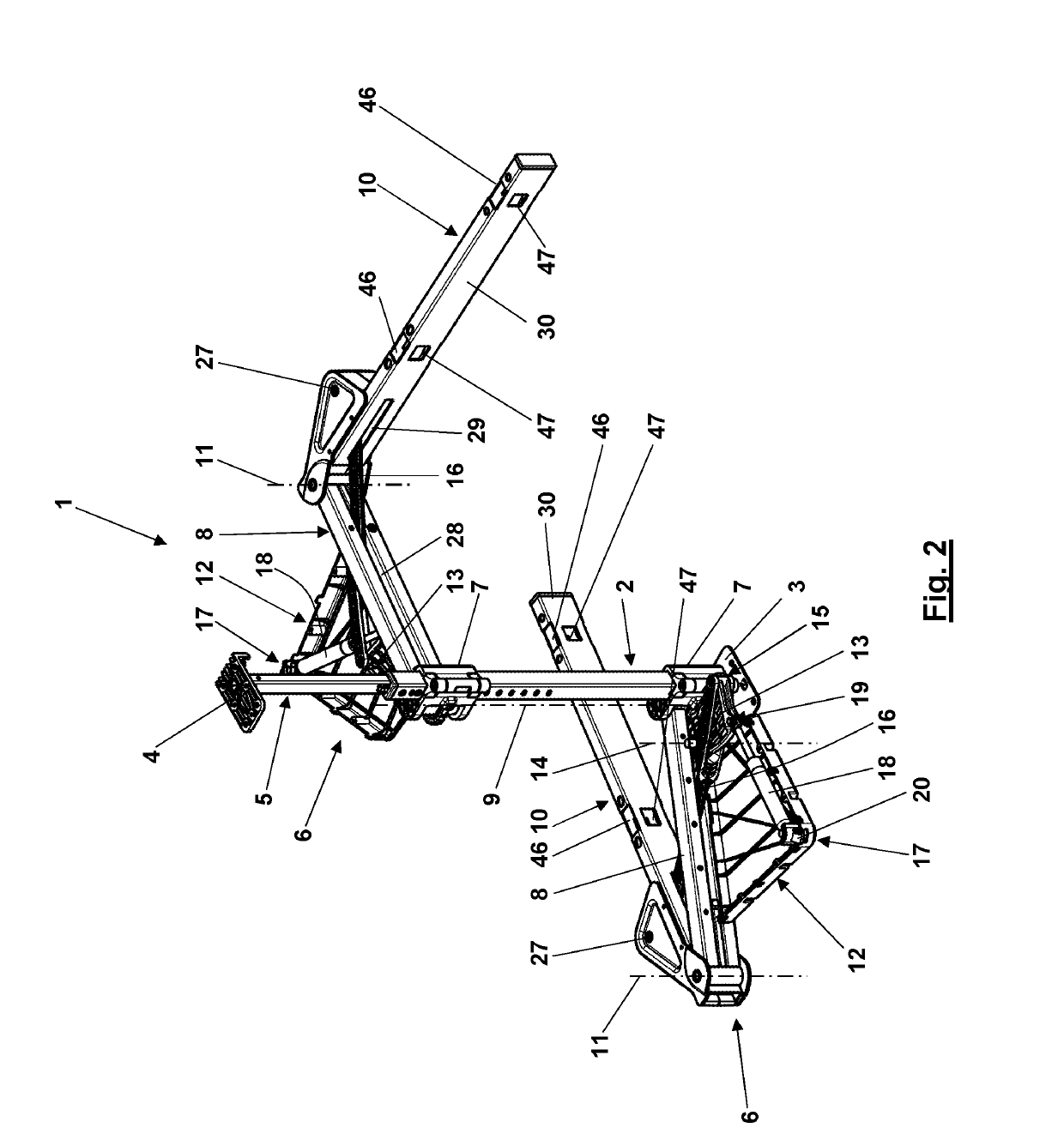
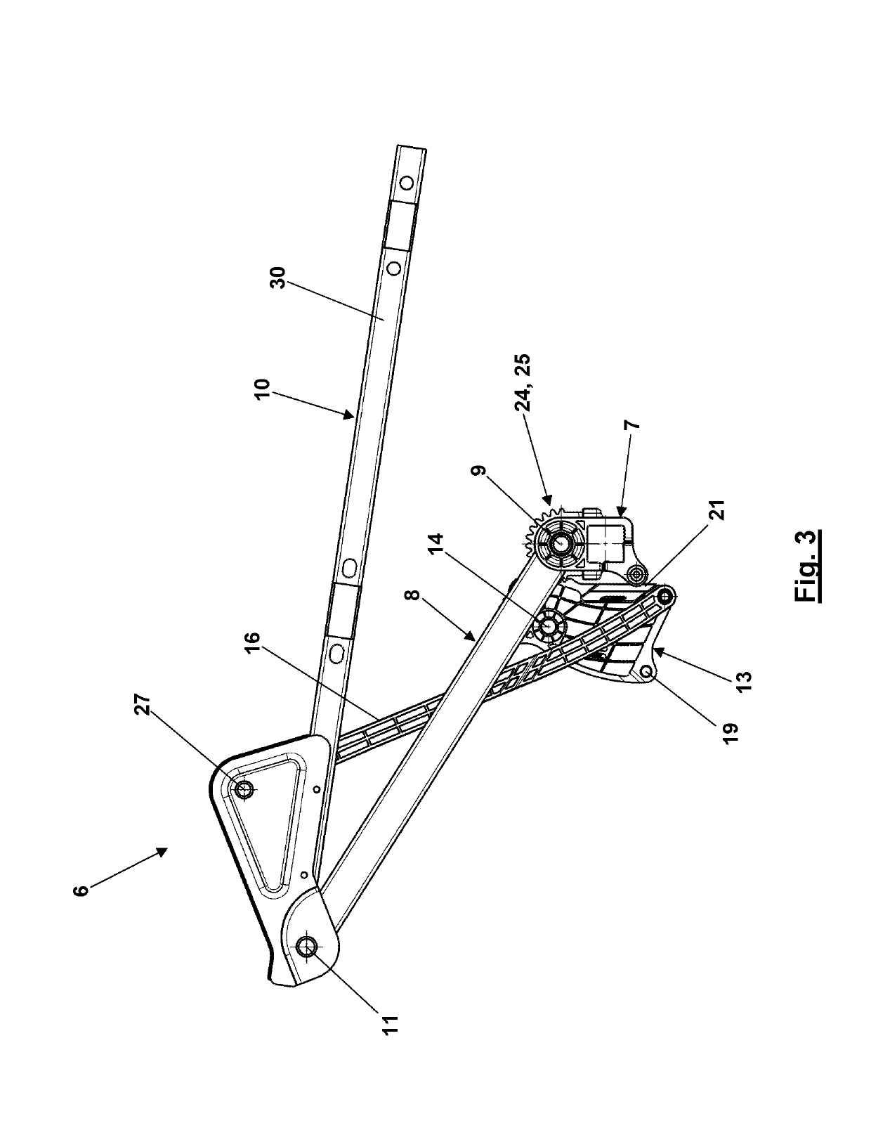
[0029]In a corner cabinet fitting for movably mounting a shelf in a corner cabinet, wherein the corner cabinet fitting has a bearing pedestal, a supporting arm mounted to the bearing pedestal such as to be pivotable in a first pivoting movement about a first vertical pivot axis, a shelf carrier mounted to the supporting arm such as to be pivotable in a second pivoting movement about a second vertical pivot axis, and a coupling mechanism coupling the second pivoting movement to the first pivoting movement, the coupling mechanism comprises two rolling elements which roll on one another and of which one rolling element is coupled to the bearing pedestal and the other rolling element is coupled to the shelf carrier.

[0030]Insofar as, in the definition of the corner cabinet fitting, it is stated that one of its parts is mounted to another of its parts such as to be pivotable about a pivot axis this generally means that the respective pivot axis is spatially fixed with regard to the other ...


PUM


Abstract

A corner cabinet fitting (1) for movably mounting of a shelf (34) in a corner cabinet (37) has a bearing pedestal (7), a supporting arm (8) which is mounted on the bearing pedestal (7) so as to be pivotable in a first pivoting movement about a first vertical pivot axis (9), a shelf carrier (10) which is mounted on the supporting arm (8) so as to be pivotable in a second pivoting movement about a second vertical pivot axis (11), and a coupling mechanism which couples the second pivoting movement to the first pivoting movement. The coupling mechanism comprises a first rolling element (24) and a second rolling elements (22), which roll on one another directly or via a belt or a chain, the first rolling element (24) being coupled to the bearing pedestal (7) and the second rolling element (22) being coupled to the shelf carrier.

Description

CROSS REFERENCE TO RELATED APPLICATIONS[0001]This application is a continuation to International Application PCT / EP2017 / 080758 with an international filing date of Nov. 29, 2017 entitled “Corner cabinet fitting for the gearwheel-controlled movable of a shelf in a corner cabinet” and claiming priority to European Patent Application No. EP 16 201 262.9 entitled “Beschlag zur zahnradgesteuerten beweglichen Lagerung eines Tablars in einem Eckschrank”, filed on Nov. 29, 2016, and now abandoned.FIELD OF THE INVENTION[0002]The invention relates to a corner cabinet fitting for movably mounting a shelf in a corner cabinet.[0003]Particularly, the invention relates to a corner cabinet fitting comprising a bearing pedestal, a supporting arm which is mounted to the bearing pedestal such as to be pivotable in a first pivoting movement about a first vertical pivot axis, a shelf carrier which is mounted to the supporting arm such as to be pivotable in a second pivoting movement about a second verti...

Claims


Application Information

Patent Timeline
IPC IPC(8): A47B46/00A47B57/00F16H51/00F16H19/00F16H21/44
CPCA47B57/00F16H51/00A47B46/00F16H21/44F16H19/005F16H19/001A47B81/002A47B77/14
Inventor SAGEL, CLAUSSAGEL, THOMAS
Owner VAUTH SAGEL HLDG
Why Eureka
Try Eureka