
Rotating resonator with flexure bearing maintained by a detached lever escapement

a flexure bearing and rotor resonator technology, applied in the direction of frequency setting mechanism, instruments, etc., can solve the problems of incompatibility with a swiss lever escapement, stiff flexible strips generally used in such rotary flexure bearings, energy loss and rate disruption, etc., to limit the chronometric effect of the unlocking phase, increase the power reserve and precision of current mechanical watches, and reduce the effect of dynamic losses

Active Publication Date: 2019-09-05
ETA SA MFG HORLOGERE SUISSE
View PDF3 Cites 2 Cited by
  • Summary
  • Abstract
  • Description
  • Claims
  • Application Information

AI Technical Summary

Benefits of technology

[0015]It is an overall object of the present invention to increase the power reserve and precision of current mechanical watches. To achieve this object, the invention combines a resonator having rotary flexure bearings with a lever escapement optimised to maintain acceptable dynamic losses and to limit the chronometric effect of the unlocking phase.

Problems solved by technology

The associated friction causes energy losses and disruptions of rate.
However, the flexible strips generally used in such rotary flexure bearings are stiffer than balance springs.
This at first sight seems incompatible with a Swiss lever type escapement.
In the absence of particular precautions, an escapement with a small angle of lift may have mediocre efficiency and cause too great a losing rate.
However, the combination of a high frequency and a low amplitude makes possible speeds of motion of the balance which are acceptable, without being too high, and thus the efficiency of the escapement is not automatically mediocre.
In short, the effect of choosing a rotary flexure bearing is that the amplitude of the balance is reduced, and it is no longer possible to use a conventional Swiss lever escapement, which requires a balance amplitude that is considerably higher than half the angle of lift, i.e higher than 25°.

Method used


Image

  • Rotating resonator with flexure bearing maintained by a detached lever escapement
  • Rotating resonator with flexure bearing maintained by a detached lever escapement
  • Rotating resonator with flexure bearing maintained by a detached lever escapement

Examples


Embodiment Construction

[0043]The invention combines a resonator having a rotary flexure bearing, to increase the power reserve and precision, with an optimised lever escapement to maintain acceptable dynamic losses and to limit the chronometric effect of the unlocking phase.

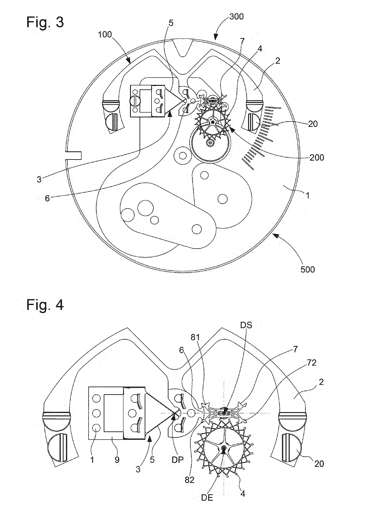
[0044]The invention therefore concerns a timepiece regulating mechanism 300, comprising, arranged on a main plate 1, a resonator mechanism 100 with a quality factor Q and an escapement mechanism 200, which is subjected to the torque of drive means 400, comprised in a movement 500.

[0045]This resonator mechanism 100 includes an inertia element 2 which is arranged to oscillate with respect to plate 1. This inertia element 2 is subjected to the action of elastic return means 3 directly or indirectly secured to plate 1. Inertia element 2 is arranged to cooperate indirectly with an escape wheel set 4, particularly an escape wheel, which is comprised in escapement mechanism 200 and pivots about an escapement axis DE.

[0046]According to the inv...


PUM


Abstract

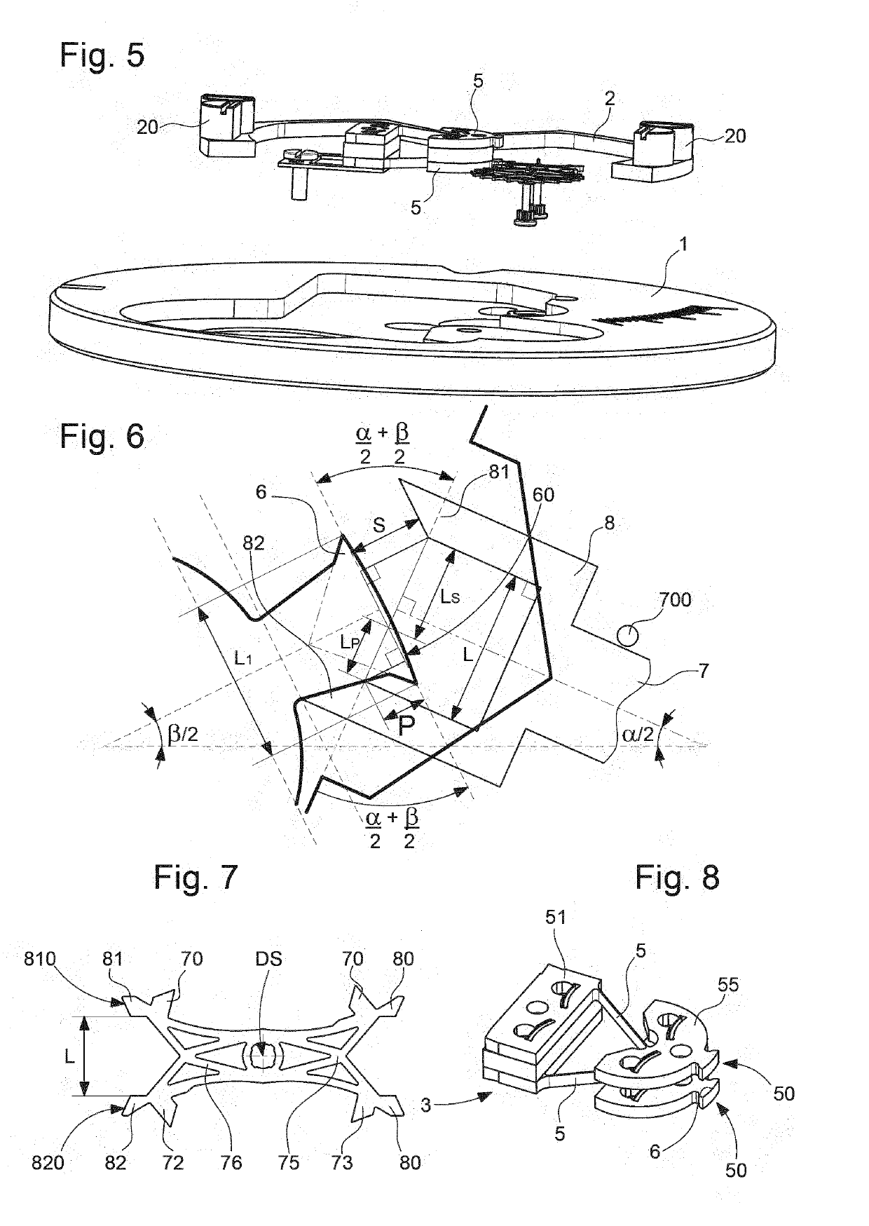
Timepiece regulator comprising a detached lever escapement mechanism, and a resonator with a quality factor Q including an inertia element including an impulse pin cooperating with a fork of the lever, subjected to the return force of two flexible strips attached to the plate, defining a virtual pivot having a main axis (DP), the lever pivoting about a secondary axis (DS), and the lift angle (β) of the resonator, during which the impulse pin is in contact with the fork, is less than 10°, and the ratio IB / IA between the inertia IB of the inertia element with respect to the main axis (DP) and the inertia IA of the lever with respect to the secondary axis (DS) is greater than 2Q·α2 / (0.1·π·β2), where α is the lift angle of the lever corresponding to the maximum angular travel of the fork.

Description

FIELD OF THE INVENTION[0001]The invention concerns a timepiece regulating mechanism, comprising, arranged on a main plate, a resonator mechanism with a quality factor Q, and an escapement mechanism which is subjected to the torque of drive means comprised in a movement, said resonator mechanism comprising an inertial element arranged to oscillate with respect to said plate, said inertial element being subjected to the action of elastic return means directly or indirectly fixed to said plate, and said inertia element being arranged to cooperate with an escape wheel set comprised in said escapement mechanism.[0002]The invention also concerns a timepiece movement comprising drive means, and such a regulating mechanism, whose escapement mechanism is subjected to the torque of these drive means.[0003]The invention also concerns a watch, more particularly a mechanical watch, including such a movement, and / or such a regulating mechanism.[0004]The invention concerns the field of timepiece r...

Claims


Application Information

Patent Timeline
Patent Type & Authority Applications(United States)
IPC IPC(8): G04B15/08G04B15/14G04B17/28G04B18/02
CPCG04B15/08G04B18/02G04B17/28G04B15/14G04B17/045G04B17/26G04B31/00
Inventor WINKLER, PASCALHELFER, JEAN-LUCDI DOMENICO, GIANNI
Owner ETA SA MFG HORLOGERE SUISSE
Learn More