Digital 3D Infrared Slit lamp with Pupil measurement

a technology pupil measurement, which is applied in the field of infrared slit lamps with pupil measurement, to achieve the effect of enhancing the evaluation of specific ocular tissu

Active Publication Date: 2019-09-05
MCWHERTER IAN W
View PDF5 Cites 4 Cited by
  • Summary
  • Abstract
  • Description
  • Claims
  • Application Information

AI Technical Summary

Benefits of technology

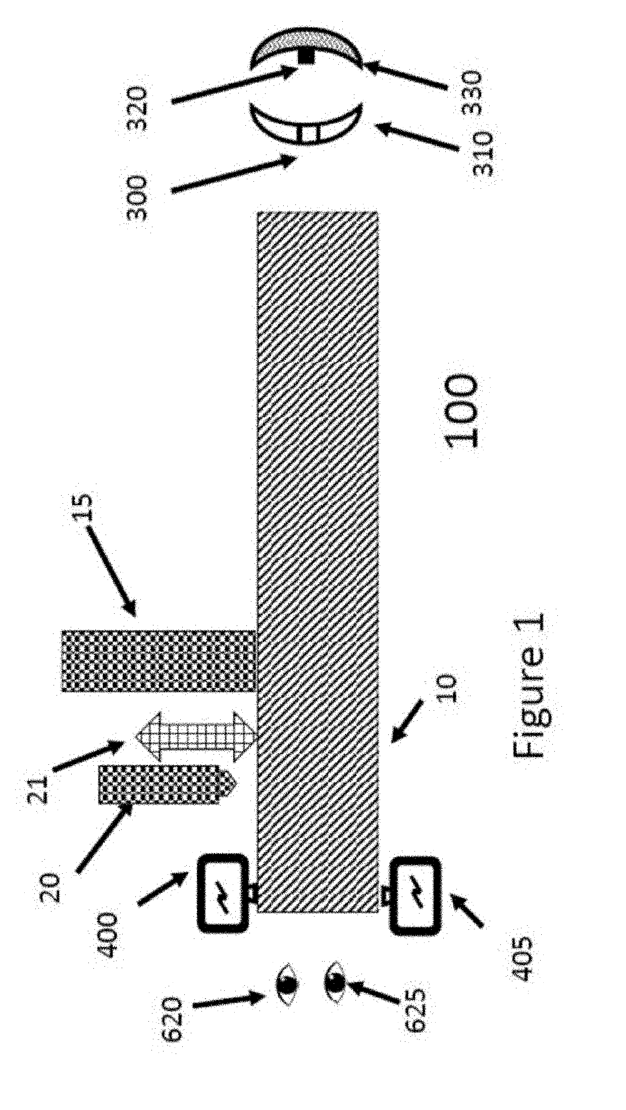
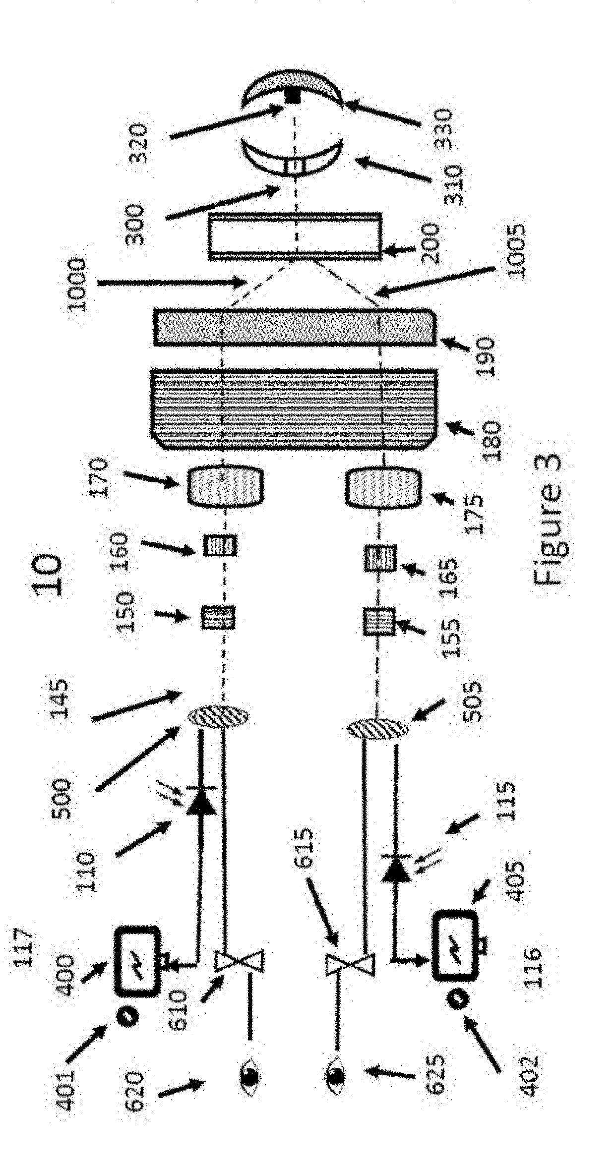
[0011]The solid-state lamp means is conveniently two or more light emitting diodes. At least one LED capable of emitting visible light and another LED being capable of emitting infrared light. Additional, wavelength of lights can also be included in the slit lamp to enhance the evaluation of specific ocular tissue.

Problems solved by technology

This is due to limitations from reflections from ocular structures but also due to the amount of light that a patient can comfortably tolerate during an examination.

Method used


Image

  • Digital 3D Infrared Slit lamp with Pupil measurement
  • Digital 3D Infrared Slit lamp with Pupil measurement
  • Digital 3D Infrared Slit lamp with Pupil measurement

Examples


Embodiment Construction

[0036]While various aspects and features of certain embodiments have been summarized above, the following detailed description illustrates a few exemplary embodiments in further detail to enable one skilled in the art to practice such embodiments. The described examples are provided for illustrative purposes and are not intended to limit the scope of the invention.

[0037]In the following description, for the purposes of explanation, numerous specific details are set forth in order to provide a thorough understanding of the described embodiments. It will be apparent to one skilled in the art, however, that other embodiments of the present invention may be practiced without some of these specific details. Several embodiments are described herein, and while various features are ascribed to different embodiments, it should be appreciated that the features described with respect to one embodiment may be incorporated with other embodiments as well. By the same token, however, no single fea...


PUM


Abstract

A device and method of ophthalmic diagnosis of lesions on retina utilizing a slit lamp apparatus with a pupil reader and at least one visible LED and one Infrared LED to detect a lesion on the retina of an eye.

Description

CROSS-REFERENCE TO RELATED APPLICATION[0001]This application claims priority from U.S. provisional patent application Ser. No. 62 / 636,867, filed Mar. 1, 2018 entitled Digital 3D slit lamp which is hereby incorporated by reference herein for all purposes.STATEMENT REGARDING FEDERALLY SPONSORED RESEARCH OR DEVELOPMENT[0002]The research for the Patent “Digital 3D Infrared Slit lamp with Pupil measurement” was not funded by any federally sponsored research or development.DESCRIPTIONField of Disclosure[0003]This invention relates generally in one aspect to slit-lamps for use in ophthalmic diagnosis and treatment. In another aspect, the invention is concerned with the application of a slit-lamp to measure metabolic activity with IR light.Background of the Invention[0004]The cornea of the eye is essential for good vision. It is the outermost tissue of the eye and functions like a window allowing the entry of light into the eye. An established branch of ophthalmic medicine is the examinatio...

Claims


Application Information

Patent Timeline
Patent Type & Authority Applications(United States)
IPC IPC(8): A61B3/135A61B3/11A61B3/15
CPCA61B3/135A61B3/112A61B3/12A61B3/107A61B3/15A61B3/0008A61B3/117
Inventor MCWHERTER, IAN W.
Owner MCWHERTER IAN W
Why Eureka
Try Eureka