
Trigger Circuitry for Fast, Low-Power State Transitions

a state transition and trigger circuit technology, applied in pulse technique, process and machine control, instruments, etc., can solve the problems of reducing efficiency and adding current, and achieve the effects of fast rising and falling edges, relatively little power consumption, and wide operating voltage rang

Active Publication Date: 2019-08-29
COGNIPOWER
View PDF0 Cites 7 Cited by
  • Summary
  • Abstract
  • Description
  • Claims
  • Application Information

AI Technical Summary

Benefits of technology

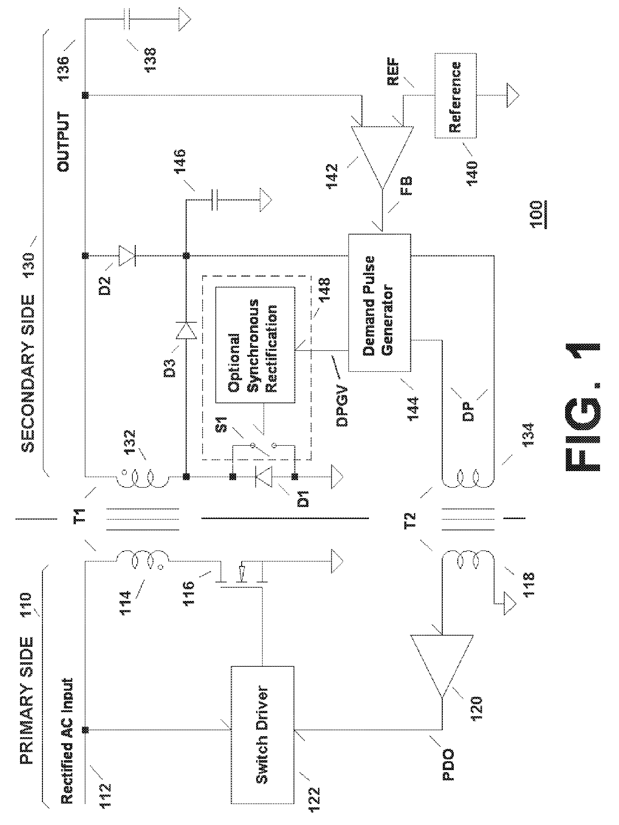
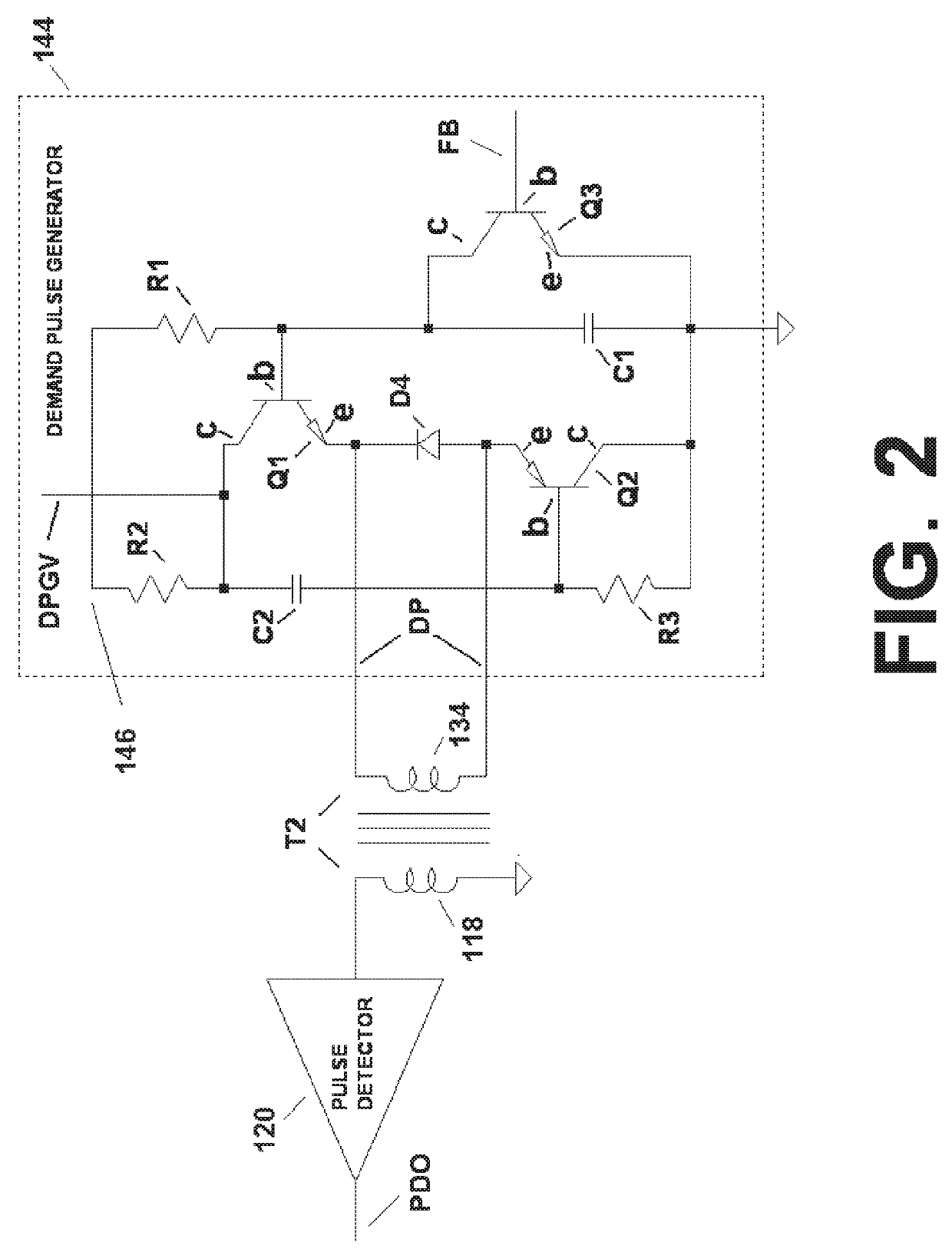
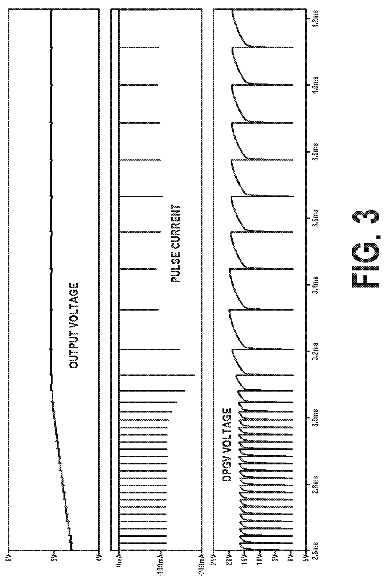
The current pulse generator described in the patent can produce fast current pulses with little power consumption. It is tolerant of different voltages and can make a wide range of pulses. It can also have a preset maximum output pulse frequency.

Problems solved by technology

That additional current drawn will necessarily reduce efficiency.

Method used


Image

  • Trigger Circuitry for Fast, Low-Power State Transitions
  • Trigger Circuitry for Fast, Low-Power State Transitions
  • Trigger Circuitry for Fast, Low-Power State Transitions

Examples


Embodiment Construction

[0025]Detailed illustrative embodiments of the present invention are disclosed herein. However, specific structural and functional details disclosed herein are merely representative for purposes of describing example embodiments of the present invention. The present invention may be embodied in many alternate forms and should not be construed as limited to only the embodiments set forth herein. Further, the terminology used herein is for the purpose of describing particular embodiments only and is not intended to be limiting of example embodiments of the invention.

[0026]As used herein, the singular forms “a,”“an,” and “the,” are intended to include the plural forms as well, unless the context clearly indicates otherwise. It further will be understood that the terms “comprises,”“comprising,”“includes,” and / or “including,” specify the presence of stated features, steps, or components, but do not preclude the presence or addition of one or more other features, steps, or components. It ...


PUM


Abstract

An n-type transistor and a p-type transistor are connected in series such that, when the two transistors are turned on, current flows from the collector of the n-type transistor to the collector of the p-type transistor. A positive-feedback capacitor is connected between the collector of one transistor and the base of the other transistor. The two transistors turn on together when the base voltage of the n-type transistor exceeds the base voltage of the p-type transistor by at least the sum of the turn-on threshold voltages of the two transistors and (i) the two transistors turn off together when the base voltage of the n-type transistor fails to exceed the base voltage of the p-type transistor by at least that sum. The positive-feedback capacitor ensures that the two transistors turn fully on and off together. In certain embodiments, the circuitry can be controlled to operate as a current pulse generator.

Description

CROSS-REFERENCE TO RELATED APPLICATIONS[0001]This application claims the benefit of the filing date of U.S. provisional application No. 62 / 635,584, filed on Feb. 27, 2018 as attorney docket no. 1254.027PROV, and U.S. provisional application No. 62 / 754,628, filed on Nov. 2, 2018 as attorney docket no. 1254.027PROV2, the teachings of both of which are incorporated herein by reference in their entirety.BACKGROUNDField of the Invention[0002]The present invention relates to electronics and, more particularly but not exclusively, to circuits having state transitions, such as current pulse generators used in power converters that perform demand pulse regulation such as described in U.S. Pat. No. 9,071,152 (“the '152 patent”), the teachings of which are incorporated herein by reference in their entirety.Description of the Related Art[0003]This section introduces aspects that may help facilitate a better understanding of the invention. Accordingly, the statements of this section are to be re...

Claims


Application Information

Patent Timeline
Patent Type & Authority Applications(United States)
IPC IPC(8): H02M7/155H02M3/157H04L7/033
CPCH02M7/1557H04L7/0338H02M3/157H03K17/30H03K19/00307H03K19/00353
Inventor LAWSON, THOMAS E.
Owner COGNIPOWER
Learn More