
Pixel structure

a pixel and structure technology, applied in the field of pixel technology, can solve the problems of reducing too large distances between pixels, and achieve the effects of reducing the influence of electric fields, reducing mura phenomenon, and effectively improving the display quality of pixels

Active Publication Date: 2019-08-29
E INK HLDG INC
View PDF0 Cites 284 Cited by
  • Summary
  • Abstract
  • Description
  • Claims
  • Application Information

AI Technical Summary

Benefits of technology

This patent describes a way to improve the quality of a display by reducing the impact of electrical signals on certain parts of the show. By using special lines that are constantly at a certain voltage, the electric field of the signals is minimized, which results in less "mura" (a visual distortion) and better overall display quality.

Problems solved by technology

In a large panel, in order to reduce a width of a frame, a number of data selection lines are increased, which result in too large distances between pixels.
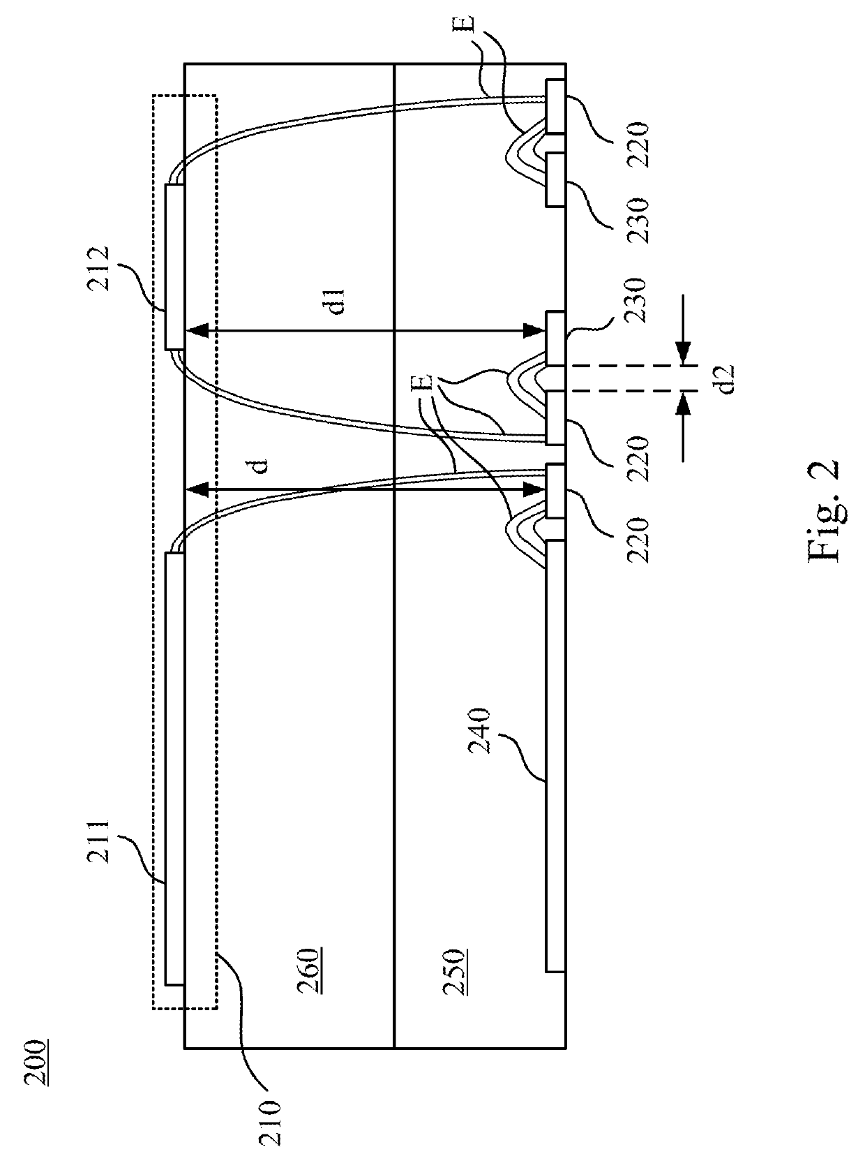
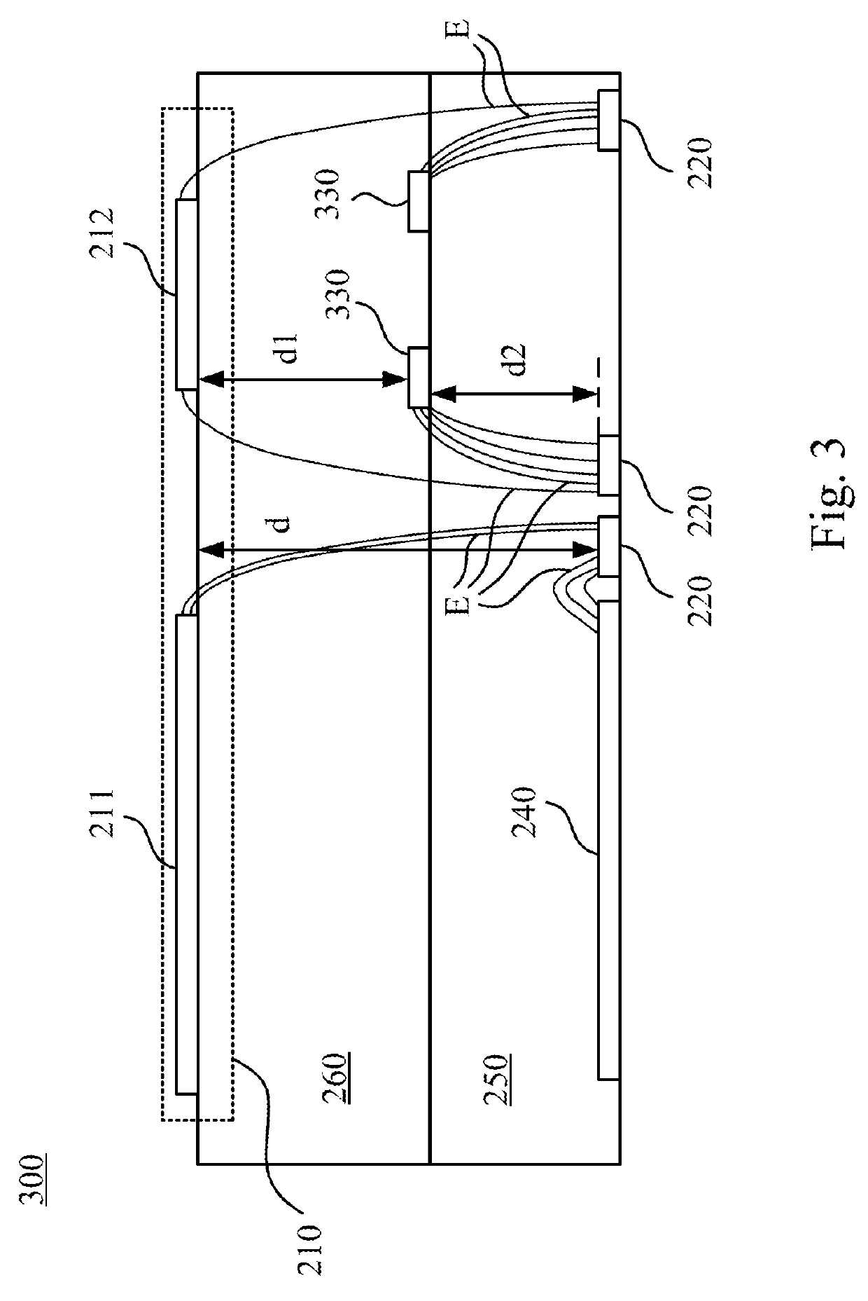
However, induced electric fields of the data selection lines affect the pixel electrodes, and thus reduce display quality of the pixels.

Method used


Image

  • Pixel structure
  • Pixel structure
  • Pixel structure

Examples


Embodiment Construction

[0012]In order to make the description of the disclosure more detailed and comprehensive, reference will now be made in detail to the accompanying drawings and the following embodiments. However, the provided embodiments are not used to limit the ranges covered by the present disclosure; orders of step description are not used to limit the execution sequence either. Any devices with equivalent effect through rearrangement are also covered by the present disclosure.

[0013]The terminology used herein is for the purpose of describing particular embodiments only and is not intended to be limiting of the disclosure. As used herein, the singular forms “a,”“an” and “the” are intended to include the plural forms as well, unless the context clearly indicates otherwise. It will be further understood that the terms “comprises” and / or “comprising,” or “includes” and / or “including” or “has” and / or “having” when used in this specification, specify the presence of stated features, regions, integers...


PUM

PropertyMeasurementUnit
distanceaaaaaaaaaa
pixel voltageaaaaaaaaaa
areaaaaaaaaaaa

Abstract

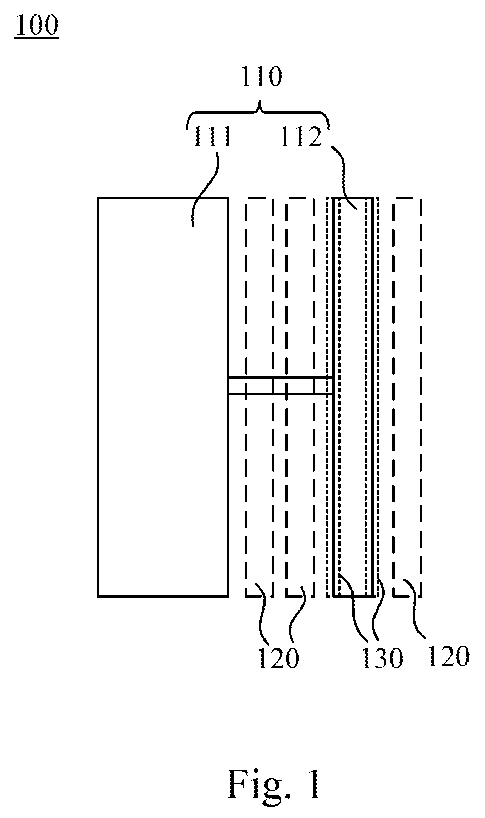
A pixel structure includes a pixel electrode, a data selection line and an isolation line. The isolation line is disposed along the pixel electrode. The pixel electrode is configured to store a pixel voltage. The data selection line is configured to transmit a data signal. The isolation line is configured to reduce an influence of an electric field of the data signal on the pixel voltage of the pixel electrode. A projection area of the isolation line is overlapped with a projection area of the pixel electrode.

Description

RELATED APPLICATIONS[0001]This is a Continuation Application of the U.S. application Ser. No. 15 / 649,614, filed Jul. 13, 2017, which claims priority to Chinese Application Serial Number 201610907122.8, filed Oct. 19, 2016, which is herein incorporated by reference.BACKGROUNDTechnical Field[0002]The present invention relates to a pixel technology. More particularly, the present invention relates to a pixel structure.Description of Related Art[0003]In a large panel, in order to reduce a width of a frame, a number of data selection lines are increased, which result in too large distances between pixels. A bridge connection is used to increase areas of pixel electrodes and reduce the distances between the pixels. However, induced electric fields of the data selection lines affect the pixel electrodes, and thus reduce display quality of the pixels.SUMMARY[0004]An aspect of the present disclosure is to provide a pixel structure including a pixel electrode, a data selection line and an iso...

Claims


Application Information

Patent Timeline
Patent Type & Authority Applications(United States)
IPC IPC(8): H01L27/12G02F1/1362
CPCG02F1/1362H01L27/124G09F9/30G02F1/133345G02F1/134363G02F2201/123G02F2201/128
Inventor LI, JI-YUANFRENCH, IANLIN, SAN-LONGLIANG, KUANG-HENGTSAI, SHU-FENCHEN, JIA-HUNG
Owner E INK HLDG INC
Learn More