Eureka AIR delivers breakthrough ideas for toughest innovation challenges, trusted by R&D personnel around the world.

Spatial radiometric correction of an optical system having a color filter mosaic

a color filter mosaic and optical system technology, applied in the field of spatial radiometric correction of optical systems, can solve problems such as the difficulty of directly measuring such a point spread function

Active Publication Date: 2019-08-22
RAYTHEON CO
View PDF0 Cites 5 Cited by
  • Summary
  • Abstract
  • Description
  • Claims
  • Application Information

AI Technical Summary

Benefits of technology

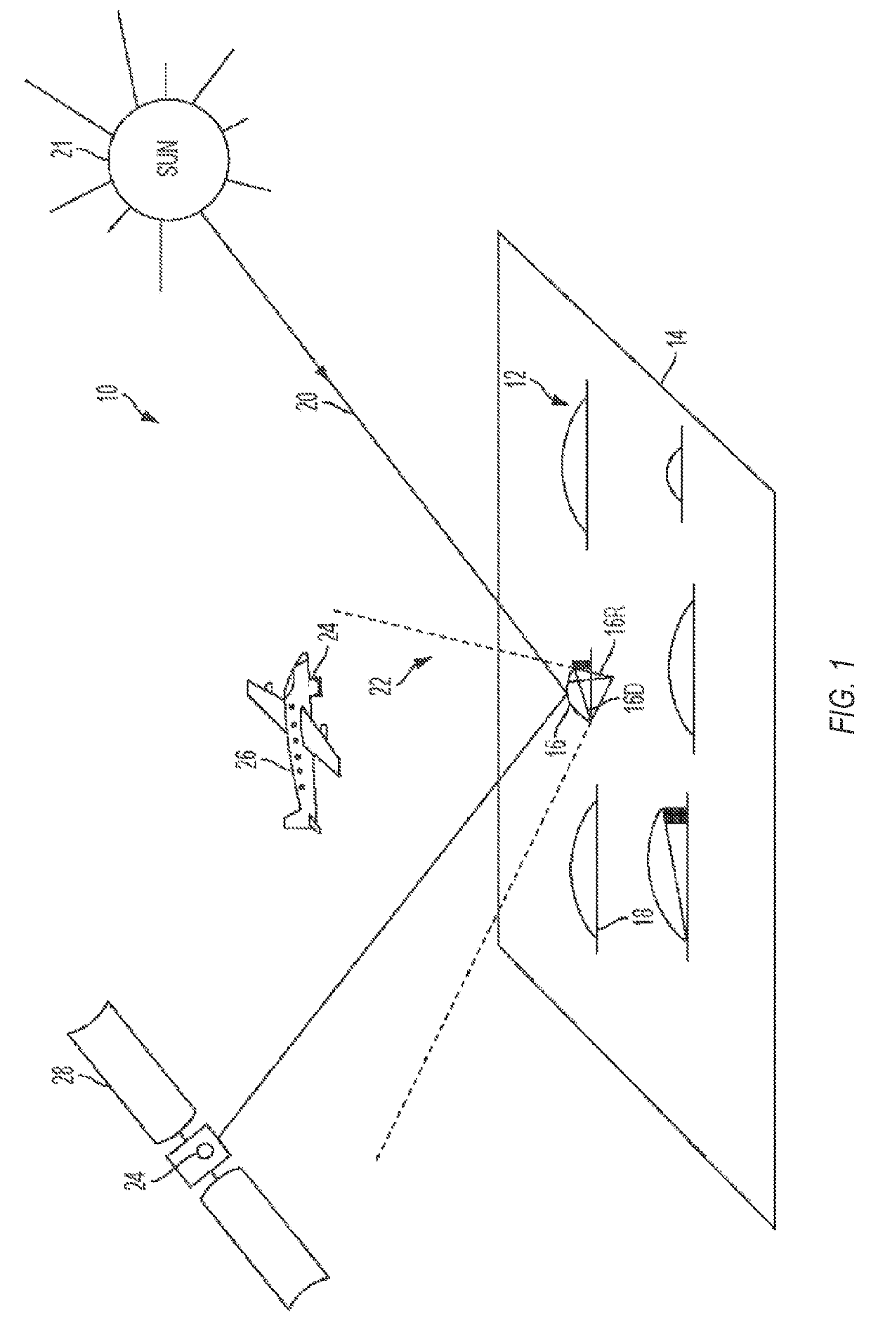
The patent describes a method for capturing and analyzing images of a ground-based scene using an optical system with a color filter mosaic. The method involves positioning the optical system above the scene and capturing two tri-color images, one with sunlight reflected from curved mirrors and one without. The two images are then subtracted to create a tri-color background-subtracted image that removes the sunlight reflection. The method also includes scaling the color values of the background-subtracted image to match the reflectivity spectrum of the curved mirrors and the transmission spectrum of the color filter mosaic. The resulting single-color background-subtracted image is useful for analyzing the optical system's point-spread function. The technical effect of this method is improved image quality and analysis of the optical system's performance.

Problems solved by technology

For optical systems that include a color filter mosaic disposed on an array of sensor pixels, it can be difficult to directly measure such a point spread function.

Method used


Image

  • Spatial radiometric correction of an optical system having a color filter mosaic
  • Spatial radiometric correction of an optical system having a color filter mosaic
  • Spatial radiometric correction of an optical system having a color filter mosaic

Examples


examples

[0057]To further illustrate the device and related method disclosed herein, a non-limiting list of examples is provided below. Each of the following non-limiting examples can stand on its own, or can be combined in any permutation or combination with any one or more of the other examples.

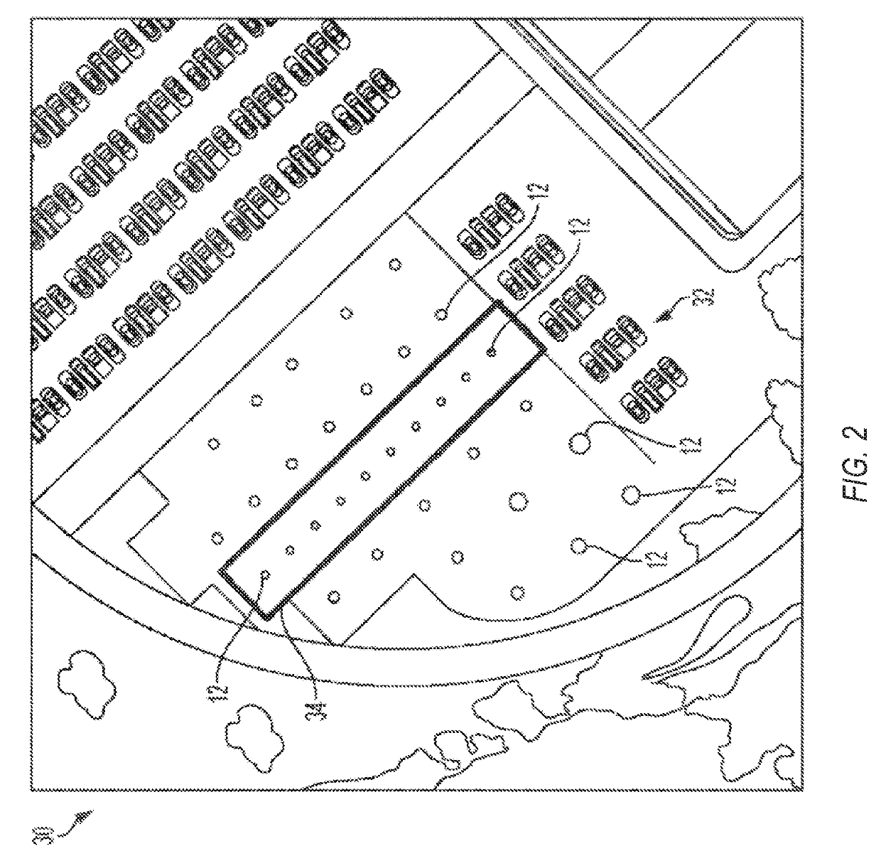
[0058]In Example 1, a method for calibrating an optical system can include: positioning the optical system above a ground-based scene, the optical system including a color filter mosaic disposed on an array of sensor pixels, the color filter mosaic configured to determine first color pixel locations, second color pixel locations, and third color pixel locations in the array of sensor pixels; capturing a first tri-color image of the scene with the optical system, the first tri-color image including a reflection of sunlight from at least one ground-based curved mirror in the scene; capturing a second tri-color image of the scene with the optical system, the second tri-color image lacking the reflectio...


PUM


Abstract

In an optical system, a color filter mosaic can determine first color pixel locations, second color pixel locations, and third color pixel locations in an array of sensor pixels. The optical system can capture overhead images, which can be subtracted to form a background-subtracted tri-color image of a reflection of sunlight from at least one ground-based curved mirror. A processor can scale color values at the first and second color pixel locations of the tri-color background-subtracted image. The processor can form a single-color background-subtracted image from the scaled color values at the first color pixel locations, the scaled color values at the second color pixel locations, and third color values at the third color pixel locations. The single-color background-subtracted image can correspond to a point spread function or a line spread function of the optical system.

Description

CROSS-REFERENCE TO RELATED APPLICATION[0001]This application claims the benefit of U.S. Provisional Application No. 62 / 633,861, filed Feb. 22, 2018, which is hereby incorporated by reference in its entirety.FIELD OF THE DISCLOSURE[0002]The present disclosure relates generally to calibrating an optical system.BACKGROUND OF THE DISCLOSURE[0003]To calibrate an optical system, it can often be desirable to measure the system's point spread function and evaluate the system's spectral radiometric response to small targets. For optical systems that include a color filter mosaic disposed on an array of sensor pixels, it can be difficult to directly measure such a point spread function. If such a measurement uses signals from just red pixels, just green pixels, or just blue pixels on a multi-wavelength detector, the signals may include holes or gaps, due to the non-contiguous nature in which the red pixels, green pixels, or blue pixels are arranged on the detector. The result is to spatially ...

Claims


Application Information

Patent Timeline
Patent Type & Authority Applications(United States)
IPC IPC(8): G06T3/40H04N5/374H04N5/345H04N9/04
CPCG06T3/4015G06T3/4007H04N5/374H04N5/345H04N9/045H04N2209/046G06T7/80G06T2207/10024H04N23/11H04N23/10H04N25/44H04N25/76
Inventor SCHILLER, STEPHEN J.
Owner RAYTHEON CO
Why Eureka
Eureka Blog
Learn More