
Tool for removing nail polish and buffing nails

a nail polish and nail technology, applied in the field of nail care tools, can solve the problems of no lamp long-lasting polish, and achieve the effect of smoothing, abradering, and polishing the nail

Active Publication Date: 2019-08-22
ALICEA GARCIA JOHANNA
View PDF0 Cites 2 Cited by
  • Summary
  • Abstract
  • Description
  • Claims
  • Application Information

AI Technical Summary

Benefits of technology

The present invention is a nail care tool with an ergonomic elongated handle that prevents the applicator head or nail buffer head from touching the fingers that hold the tool. It also allows users to have greater reach when removing polish from their toenails or buffing them. The tool includes a disposable / replaceable firm applicator head that maintains its shape when in use. The operational section of the applicator head induces regular friction during cleaning, facilitating the removal process. The manual holding / release mechanism allows users to easily attach and release the applicator head or nail buffer head without having to touch it with their hands.

Problems solved by technology

Rubbing a solvent -sodden applicator head over the surface of a fingernail or toenail with regular nail polish, no lamp long-lasting polishes or the like, allows a user to remove thoroughly, neatly and efficiently the coating therefrom.

Method used


Image

  • Tool for removing nail polish and buffing nails
  • Tool for removing nail polish and buffing nails
  • Tool for removing nail polish and buffing nails

Examples


embodiment 20

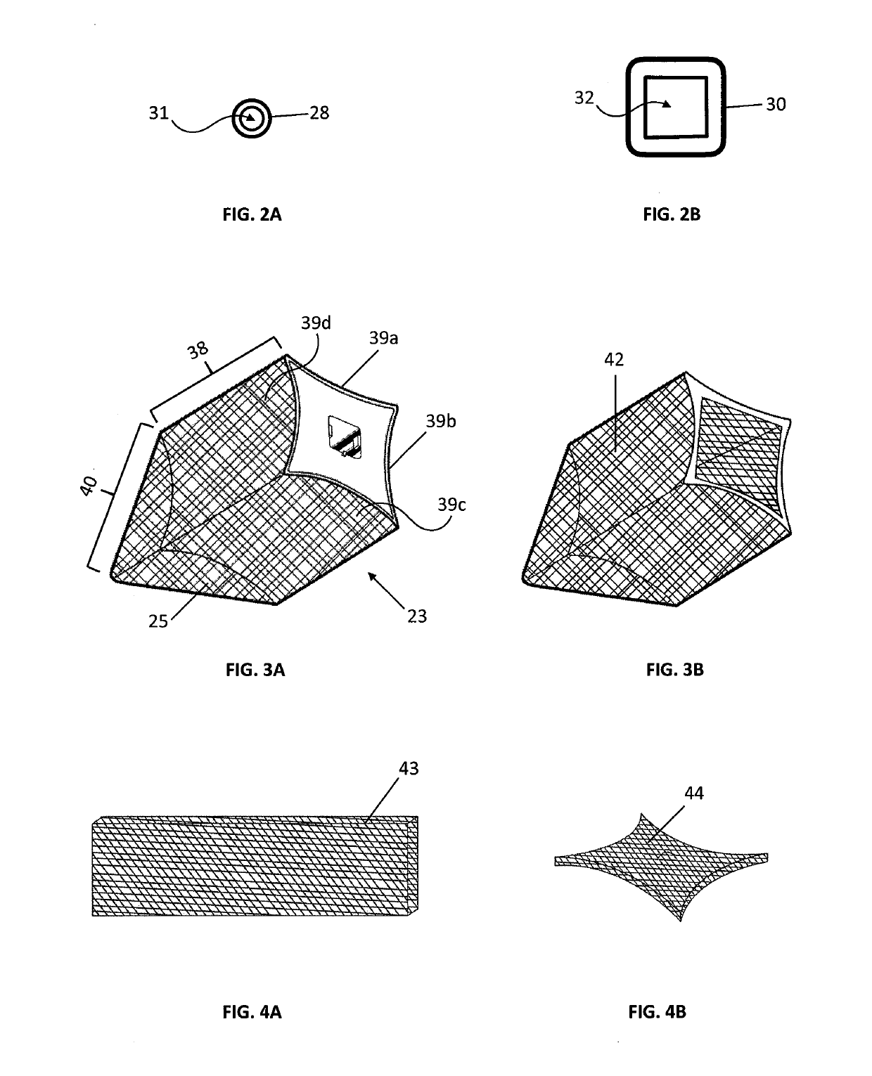
[0072]Embodiment 20 also comprises at the curved or concave sides 39a, 39b, 39c, and 39d, as well as the corresponding sides of top section 40, a lining 41 of a suitable material capable to absorb and retain fluids, such as felt, polypropylene, cotton and sponge; more preferably felt or polypropylene. Said lining of absorbent material is adhered to said sides by means of any suitable covering methods known in the art. For instance, the absorbent material may be molded in a single unit or sheath layer 42 that simulates the shape of the head 23 and further adhered to the head 23. Such single unit or sheath layer 42, illustrated in FIG. 4, may be suitably made by heat molding process, in a cap-like shape that fits to cover the upper surface of all the sides 39a, 39b, 39c, and 39d of rectangular section 38 and corresponding sides of top section 40. Subsequently, said sheath layer 42 is adhered to the head 23 using a suitable gluing, cementing or bonding mean, known in the art, that is r...

embodiment 180

[0102]With regards to head 184, it comprises a single unit body with an external geometrical shape having a tridimensional rectangular section 194 with curved or concave lateral sides 195a, 195b, 195c, and 195d, that are extended continuously into a four sides pyramidal shape top section 196. Head 184 also comprises an internally threaded opening 197, which is cooperatively adapted to cylindrical section 189 on handle 181, as shown in FIG. 23. Thus, in this embodiment 180, handle 181 is connected and disconnected to head 184 by means of inserting cylindrical section 189 on opening 197 and screwing or unscrewing it respectively.

[0103]Head cap 185 is made of plastic and simulates the external shape of head 184. This cap is intended to cover head 184 in order to protect it one it is not being used.

[0104]FIG. 24 illustrates embodiment 199 of the invention comprising same main external sections of the embodiment 180: elongated ergonomic handle 181, scraper 183, head 184, head cap 185 and...

embodiment 212

[0107]The scope of this invention also comprises embodiments directed to tools useful in buffing nails, wherein, in place of an absorbing material, an abrasive material is used. For instance, as illustrated in FIG. 27, embodiment 212 comprises an elongated ergonomic handle 213, scraper 214, head 215, head cap 216 and the same hold / release system already discussed to separate the head 23 from the handle 21.

[0108]Head 215 is connected to handle 213 by means of the same hold and release system described above for embodiment 20. Head 215 comprises a single unit body with an external geometrical shape having a tridimensional rectangular section 217 with flat lateral sides 218a, 218b, 218c, and 218d. Said flat lateral sides have adhered a resilient pad 219, having a front surface 220 with a film of adhesion material and a back surface 221 comprising a film of buffing material 222. Such resilient pad 219 may be made of foam or rubber. The buffing material, which is commercially available w...


PUM


Abstract

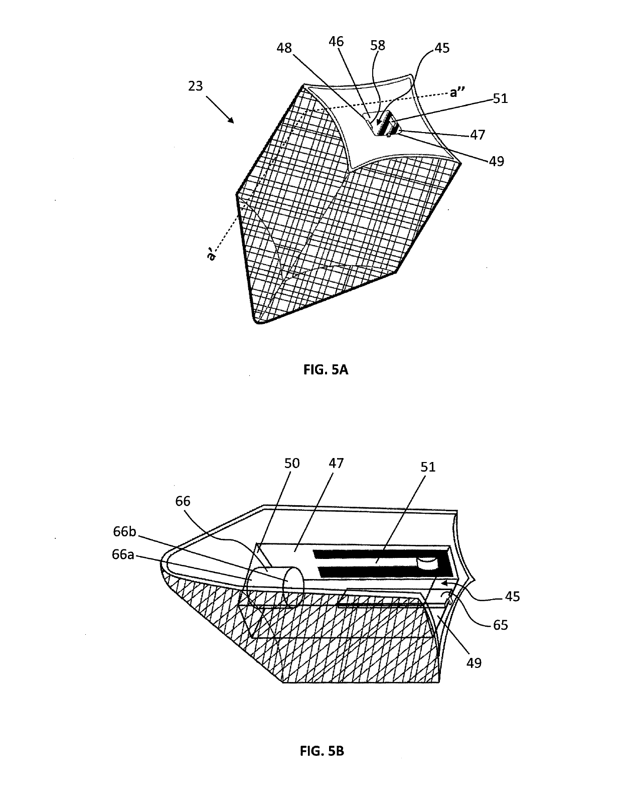
A nail care tool having an ergonomic elongated handle and a removable operational head attached to the handle is presented. The tool also has a removable scraper or end tip inserted in one of the ends of the handle, useful in cleaning critical cuticle areas. The operational head has adhered to it a lining of material commonly used in the nail care and maintenance processes; for instance, it may be a nail polish removal material or a nail buffing material. In some embodiments of the invention, the ergonomic handle and the head are interconnected in a nonpermanent manner by a male / female system; in such embodiments, the head may be engage or connected to the handle by screwing the head to the handle and, it may be disengaged or disconnected, by simply unscrewing it from the handle. In other embodiments of the invention, the handle is connected to the head by a hold / release system, allowing the User to connect the head and the handle by inserting an already assembled cartridge inside the handle into a rectangular internal cavity on the head. In order to disconnect the head from the handle, the User slides backwardly a button on the ergonomic handle without even having to touch the head. The hold / release system allows the User to easily attach or detach heads to the handle. The operational removable head required for any of the embodiments may have different shapes and operational lining materials, in order for the User to use the tool as an applicator—meaning being able to remove most of the nail polishes—or as a nail buffer.

Description

CROSS REFERENCE TO RELATED APPLICATIONS[0001]This application claims the benefit of U.S. Provisional Application No. 62 / 633524, filed on Feb. 21, 2018 and claim the benefit of its earlier date under 35 USC section 119 (e).TECHNICAL FIELD[0002]This invention relates to nail care devices and systems. More specifically, it relates to a nail care tool comprising an ergonomic handle, a replaceable head and an end tip, that allows a person to conveniently remove nail polish, buff nails and clean nails and surrounding nail areas.BACKGROUND[0003]Nail care is an essential part in the maintenance of personal hygiene. In order to maintain healthy nails, individuals must keep their fingernails and toenails well groomed at all times. The common practices of enhancing the appearance of nails comprise removing old or damaged nail polish and buffing.[0004]Modern nail polish has been on the nail care market for almost 100 years. Many individuals today, mostly women, beautify their fingernails and to...

Claims


Application Information

Patent Timeline
Patent Type & Authority Applications(United States)
IPC IPC(8): A45D29/00A45D29/12A45D29/17
CPCA45D29/007A45D29/12A45D29/17A45D2200/1018
Inventor ALICEA-GARCÍA, JOHANNA
Owner ALICEA GARCIA JOHANNA
Learn More