Eureka AIR delivers breakthrough ideas for toughest innovation challenges, trusted by R&D personnel around the world.

Unattended Railcar Motion Control System

a technology for motion control and unattended railcars, which is applied in the direction of brake control systems, brake systems, transportation and packaging, etc., can solve the problems of unattended railcars, unattended railcars, and risk of accidents from the movement of railcars

Active Publication Date: 2019-08-15
ENERSUL
View PDF0 Cites 1 Cited by
  • Summary
  • Abstract
  • Description
  • Claims
  • Application Information

AI Technical Summary

Benefits of technology

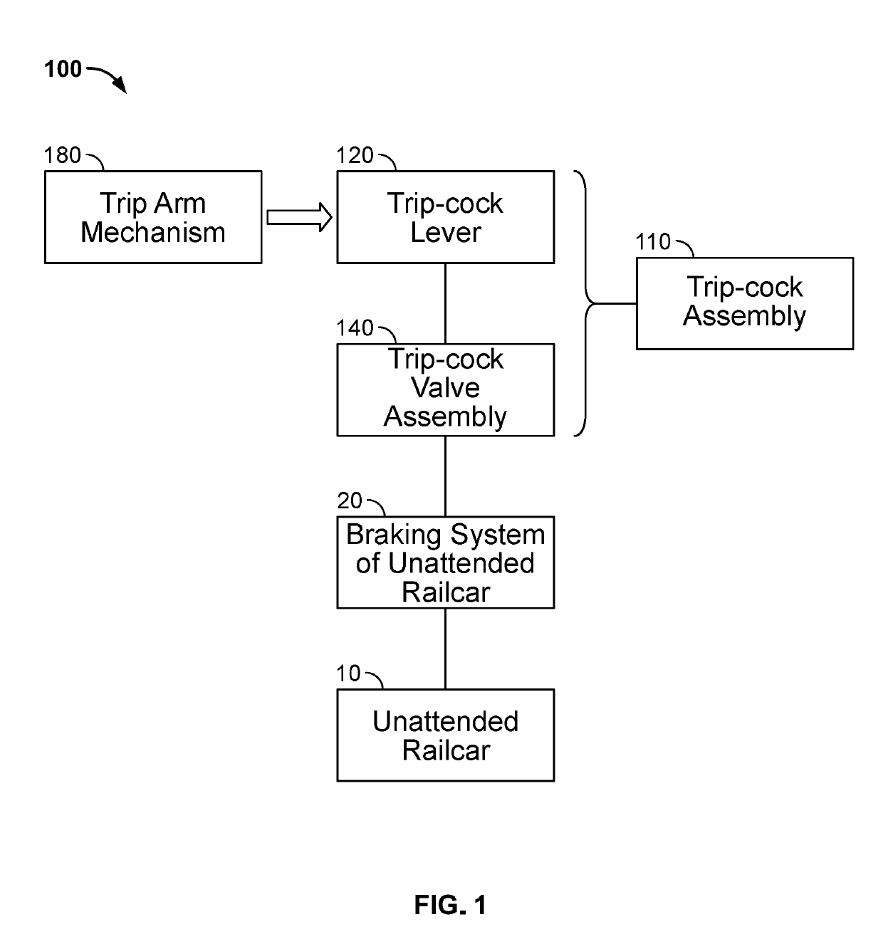
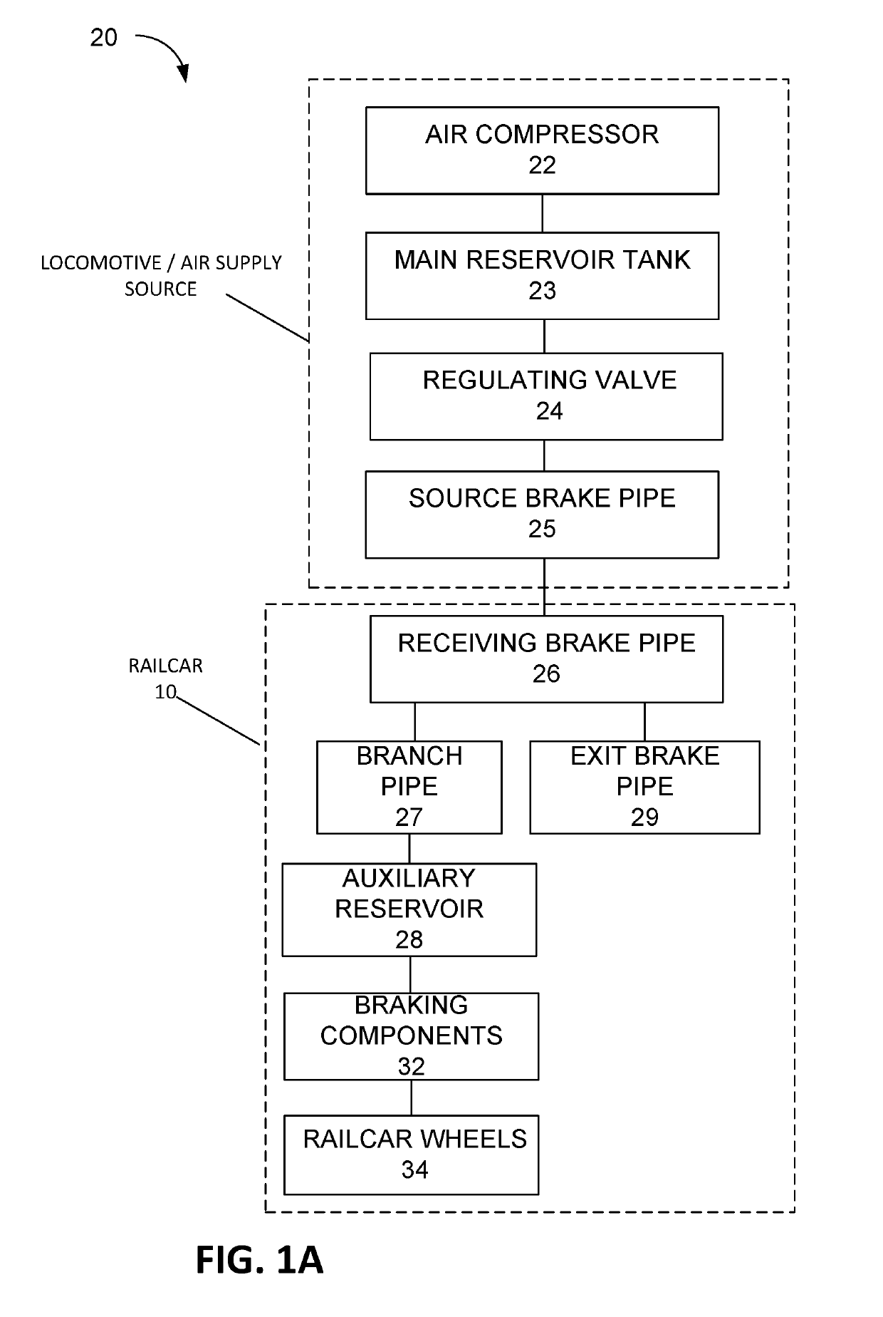
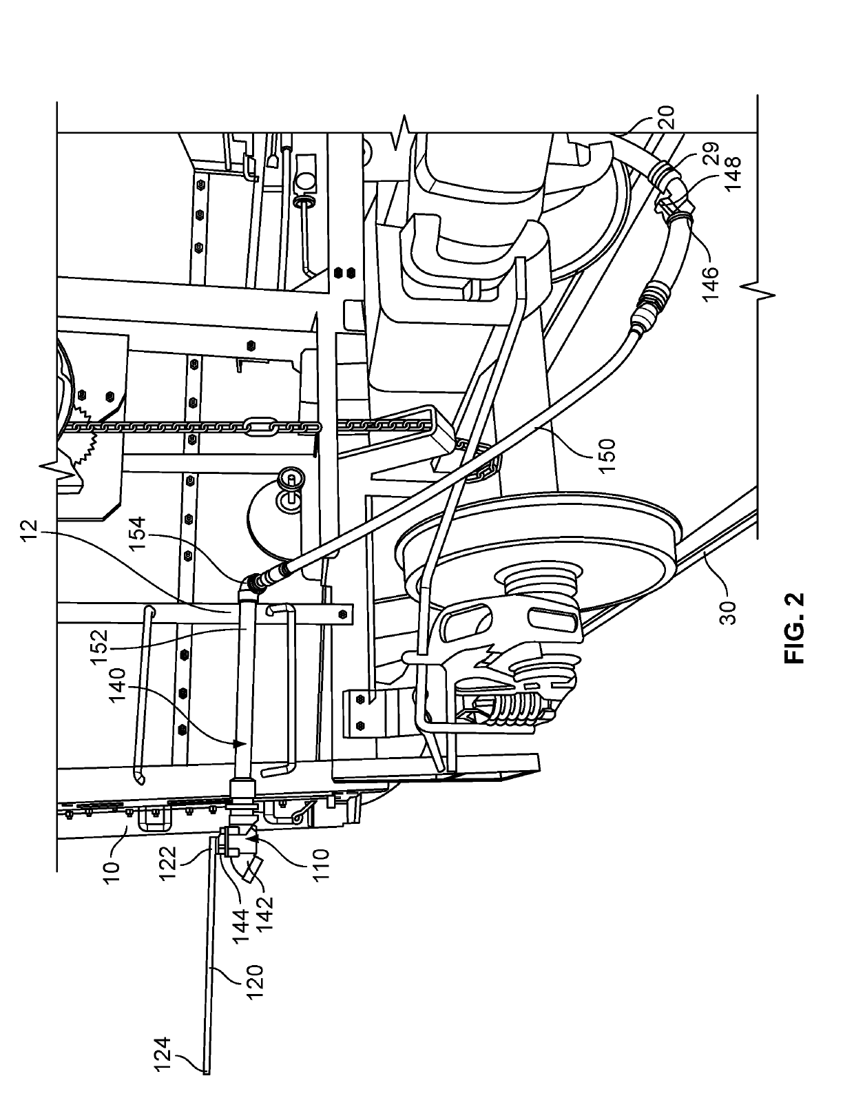
This patent describes a system for controlling the motion of an unattended railcar using a trip-cock assembly. The trip-cock assembly includes a trip-cock lever that can be adjusted from a folded position to an extended position. When the trip-cock lever is in the extended position, it contacts a trip arm on the railcar, causing the valve to release air in the braking system of the railcar. The trip-cock assembly is attached to the railcar using a mechanical connection and a flexible hose. The system also includes an air compressor, a main reservoir, a regulating valve, a source brake pipe, and a fluid injector. The fluid injector injects a fluid with a freezing point below -40°C into the braking system, and the injection is intermittent. The technical effects of this system include improved control of unattended railcars and improved safety during braking operations.

Problems solved by technology

As railcars are moved along a railyard, the railcars may be left unattended by an operator at various times. For example, a railcar may be unattended during loading and unloading of cargo to the railcar.
While left unattended, a railcar may begin to move unexpectedly or may travel beyond the designated loading or unloading point, which raises the risk of accidents from the railcar's movement or spilling of the cargo during the loading process.

Method used


Image

  • Unattended Railcar Motion Control System
  • Unattended Railcar Motion Control System
  • Unattended Railcar Motion Control System

Examples


Embodiment Construction

[0030]In the following description of various example structures and methods according to the invention, reference is made to the accompanying drawings, which form a part hereof, and in which are shown by way of illustration various example devices, systems, and environments in which aspects of the invention may be practiced. It is to be understood that other specific arrangements of parts, example devices, systems, and environments may be utilized and structural and functional modifications may be made without departing from the scope of the present invention. Also, while the terms “top,”“bottom,”“front,”“back,”“side,”“rear,” and the like may be used in this specification to describe various example features and elements of the invention, these terms are used herein as a matter of convenience, e.g., based on the example orientations shown in the figures or the orientation during typical use. The terms “substantially horizontal” and “substantially vertical” may be interpreted within...


PUM


Abstract

A method and mechanism for initiating an emergency stop for an unattended railcar is disclosed. The method may include using a trip arm placed alongside the railway tracks at a designated stop point that may contact a portable trip-cock lever arm that extends out beyond the perimeter of the railcar if the railcar reaches the stop point as it moves along the track. The trip-cock lever arm may be attached to a valve that is connected to the pneumatic brake system of the unattended railcar. As the trip-cock lever arm rotates, the valve may open to release the air pressure in the pneumatic brake system causing the brakes to engage the wheels causing the railcar to stop.

Description

CROSS-REFERENCE TO RELATED APPLICATIONS[0001]This application claims priority to U.S. Provisional Application No. 62 / 629,509 filed on Feb. 12, 2018. The above referenced application is incorporated by reference in its entirety.FIELD OF INVENTION[0002]This disclosure relates to a system for controlling the movement of unattended railway cars without direct supervision.BACKGROUND[0003]As railcars are moved along a railyard, the railcars may be left unattended by an operator at various times. For example, a railcar may be unattended during loading and unloading of cargo to the railcar. While left unattended, a railcar may begin to move unexpectedly or may travel beyond the designated loading or unloading point, which raises the risk of accidents from the railcar's movement or spilling of the cargo during the loading process.BRIEF SUMMARY[0004]This disclosure may relate to a system for controlling motion of an unattended railcar comprising a trip-cock assembly, where the trip-cock assem...

Claims


Application Information

Patent Timeline
Patent Type & Authority Applications(United States)
IPC IPC(8): B61H11/02B60T17/22B60T8/17B60T13/10
CPCB61H11/02B60T17/228B60T8/1705B60T13/10B60T13/665B60T7/18B60T8/885B60T2270/402B60T2270/413
Inventor ENGELLAND, MARK CHARLESGREER, TREVOR MICHAELSHAW, DAVID ALEXANDER
Owner ENERSUL
Why Eureka
Eureka Blog
Learn More