Damper device

a technology of damper device and damper body, which is applied in the direction of shock absorbers, liquid based dampers, mechanical instruments, etc., can solve the problems of uneven expansion and contraction of the damper device, excessive pressure in the gas chamber, and inability to stabilize the damping for

Active Publication Date: 2019-08-08
HONDA MOTOR CO LTD
View PDF7 Cites 2 Cited by
  • Summary
  • Abstract
  • Description
  • Claims
  • Application Information

AI Technical Summary

Benefits of technology

The present invention is aimed at providing a damper device that can increase rigidity while stabilizing the damping force. It can smoothly expand and contract without causing any discomfort or malfunction.

Problems solved by technology

However, the damper device disclosed in Patent document 1 poses a problem in that, when it is brought into a high temperature state by continuous use or the like, gas is expanded to cause pressure in the gas chamber to increase excessively and thus damping force is not stabilized.
For this reason, the damper device also poses a problem in that a sliding resistance between the piston rod and seal materials becomes high and thus smooth expansion and contraction of the damper device is hindered.

Method used


Image

  • Damper device
  • Damper device

Examples


first embodiment

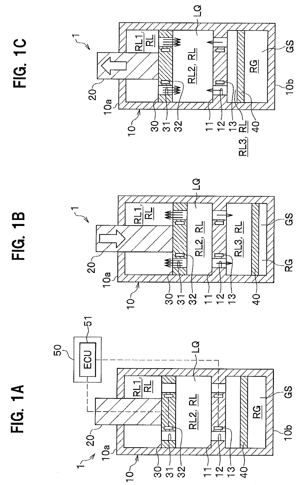
[0014]As shown in FIGS. 1A to 1C, a damper device 1 according to the present embodiment is provided with a cylinder 10, a piston rod 20, a piston 30, a free piston 40, and a control unit 50.

[0015]Moreover, the damper device 1 according to the present embodiment composes a suspension (not shown) of a four-wheeled vehicle, and in FIGS. 1A to 1C, a lower end part thereof is coupled to a wheel side (not shown) and an upper end part thereof is coupled to a vehicle body side (not shown).

[0016]As shown in FIGS. 1A to 1C, the cylinder 10 composes a lower part of the damper device 1 and a lower end thereof is coupled to the wheel side. Moreover, the cylinder 10 has a cylindrical shape of a single layer in a radial direction, and is a sealed container closed at both ends. Furthermore, the cylinder 10 is provided with a partition wall 11 inside.

[0017]The partition wall 11 is composed of a circular plate that is fixed to the cylinder 10 orthogonally to the cylinder shaft, between the piston 30 ...

second embodiment

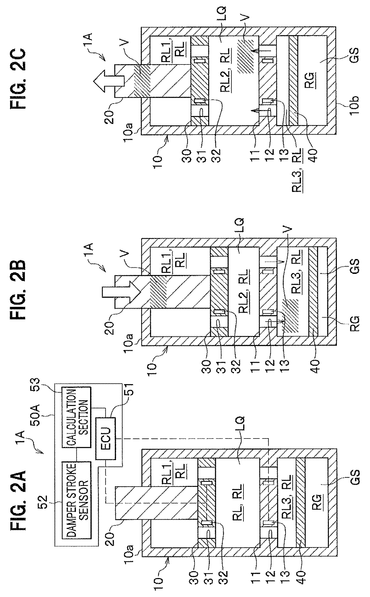
[0069]Next, a damper device 1A according to the second embodiment will be described with reference to the drawings. The same constituent element as that in the damper device 1 described above is given the same reference sign and thus duplicate explanation thereof is omitted.

[0070]As shown in FIGS. 2A to 2C, the present embodiment is different from the first embodiment described above in the configuration and control method of a control unit 50A.

[0071]The control unit 50A according to the present embodiment includes, other than the ECU 51, a damper stroke sensor 52 and a calculation section 53 (see FIG. 2A).

[0072]The damper stroke sensor 52 is adapted to measure the amount of stroke when the damper device 1 is expanded and contracted.

[0073]The calculation section 53 is adapted to calculate volume V of the piston rod 20 moving into / out of the cylinder 10, based on the product of the measured amount of stroke by the shaft diameter of the piston rod 20.

[0074]The ECU 51 controls the pist...


PUM


Abstract

A damper device provided with a single cylinder type erecting structure having a free piston includes: a partition wall fixed to the cylinder between a piston and the free piston and partitioning inside of the cylinder into spaces in an axial direction of the cylinder; a partition wall orifice composed of an orifice piercing through the partition wall; a piston orifice composed of an orifice piercing through the piston; a partition wall-side flow variable structure configured to regulate a flow rate of a viscous fluid passing through the partition wall orifice; a piston-side flow variable structure configured to regulate a flow rate of the viscous fluid passing through the piston orifice; and a control unit configured to control the partition wall-side flow variable structure and the piston-side flow variable structure.

Description

CROSS-REFERENCE TO RELATED APPLICATION[0001]This application is based upon and claims priority from the Japanese Patent Application No. 2018-020744, filed on Feb. 8, 2018, the entire contents of which are incorporated herein by reference.BACKGROUND OF THE INVENTION1. Field of the Invention[0002]The present invention relates to a damper device adapted to damp and absorb vibration and shock.2. Description of the Related Art[0003]As conventional means for damping and absorbing vibration and shock, a damper device of a type that allows a piston fixed to a piston rod to be reciprocated in a cylinder has been widely employed, as disclosed in Patent document 1 (Japanese Patent Application Publication No. 2007-187176).[0004]The damper device disclosed in Patent document 1 includes, other than the piston rod and the piston, a free piston disposed in the cylinder so as to partition the inside of the cylinder into a liquid chamber into which a magnetic viscous fluid is filled, and a gas chambe...

Claims


Application Information

Patent Timeline
IPC IPC(8): F16F15/02F16F9/18
CPCF16F15/02F16F9/18F16F15/027F16F15/04F16F9/46F16F9/535
Inventor SOGAWA, NAOKIKOMORI, KENTAROFUJIMOTO, GAKUYO
Owner HONDA MOTOR CO LTD
Why Eureka
Try Eureka