Centrifugal blower
a centrifugal blower and centrifugal technology, which is applied in the direction of non-positive displacement fluid engines, radial flow pumps, pump components, etc., can solve the problems of insufficient reduction of the occurrence of separation of the air flow from the blade, insufficient reduction of the and insufficient noise reduction effect of the conventional turbo fan described abov
- Summary
- Abstract
- Description
- Claims
- Application Information
AI Technical Summary
Benefits of technology
Problems solved by technology
Method used
Image

Examples
first embodiment
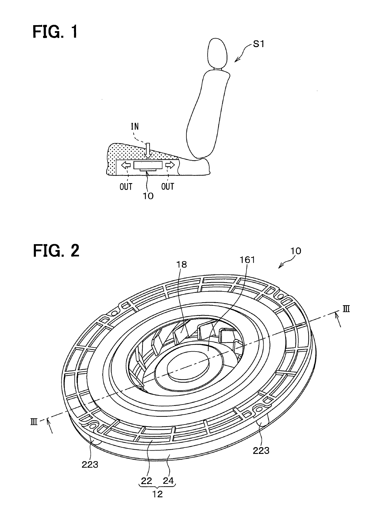
[0063]As shown in FIG. 1, the blower 10 of the present embodiment is used in a seat air conditioner for a vehicle. The blower 10 is housed in a seat 51 on which an occupant sits. The blower 10 draws in an air from a surface of the seat 51 on which the occupant sits. The blower 10 blows out the air inside the seat 51. The air blown out from the blower 10 is discharged from a portion of the seat S 1 other than the surface on which the occupant sits.
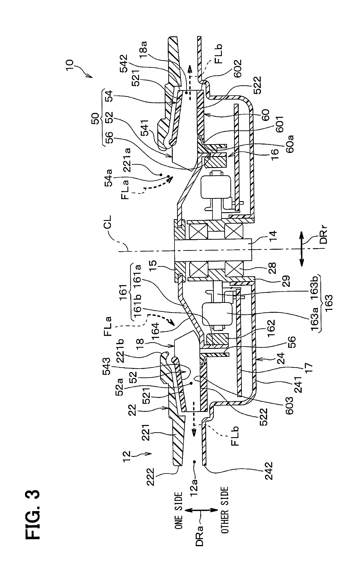
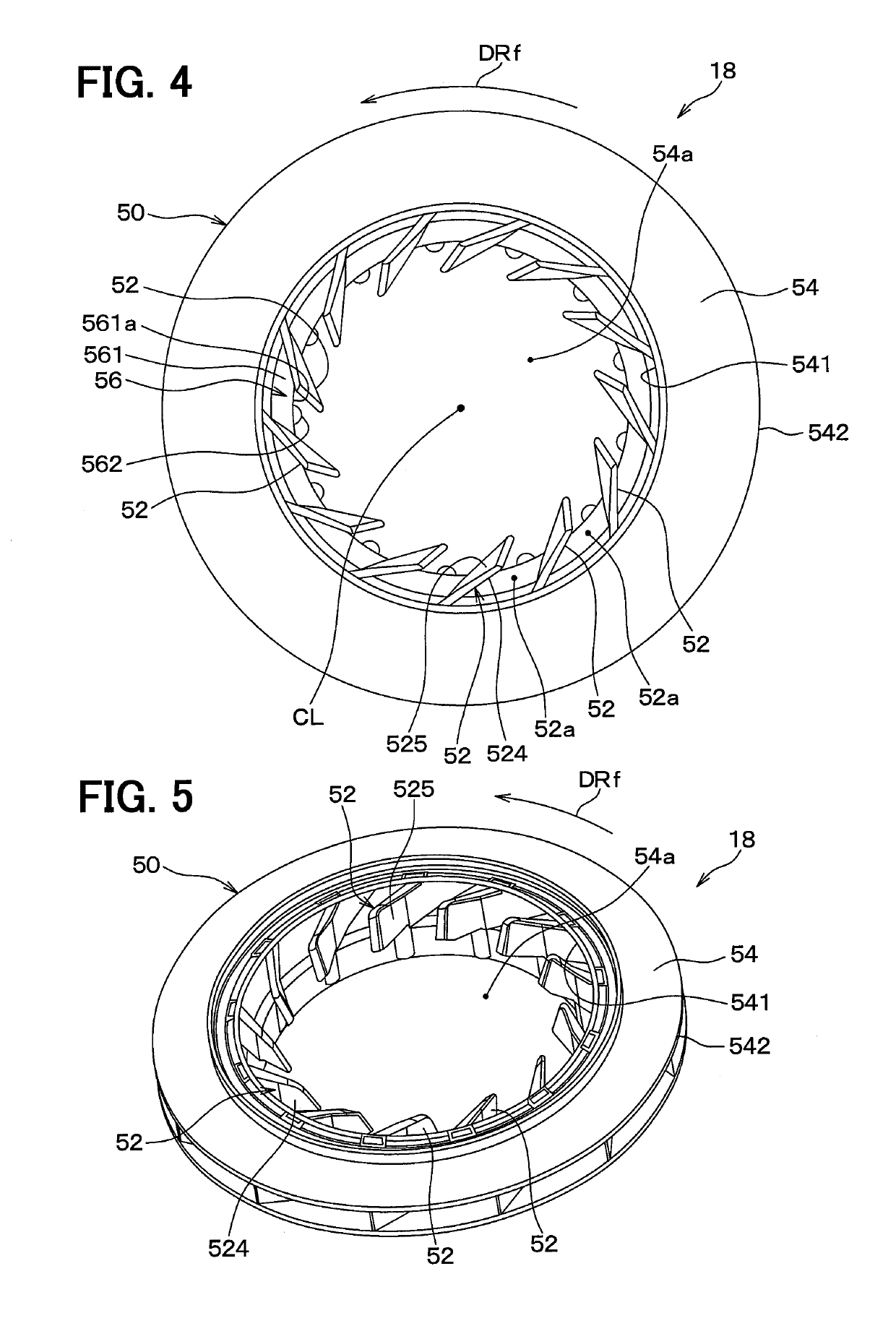
[0064]As shown in FIGS. 2 and 3, the blower 10 is a centrifugal blower. In detail, the blower 10 is a turbo type blower. As shown in FIG. 3, the blower 10 includes a casing 12, a rotation shaft 14, a rotation shaft housing 15, an electric motor 16, an electronic board 17, a turbo fan 18, a bearing 28, a bearing housing 29, and the like. An arrow DRa in FIG. 3 indicates a fan axis center direction. A fan axis center CL coincides with an axis center of the rotation shaft 14. The fan axis center direction is also referred to as a rotation axis...
second embodiment
[0146]As shown in FIGS. 18 and 19, in the present embodiment, a placement location of multiple ribs 562 is changed from that in the first embodiment. The other configuration of the blower 10 is the same as that of the first embodiment. FIG. 18 is a diagram of a turbo fan 18 as viewed from the other side in a fan axis center direction DRa in parallel to the fan axis center direction DRa according to the present embodiment. FIG. 19 is an enlarged view of one blade 52 in FIG. 18.
[0147]As shown in FIG. 19, each of the multiple ribs 562 is located on a lower surface 52d of the blade 52. The lower surface 52d of the blade 52 is the other side blade end portion 522 shown in FIG. 3.
[0148]More specifically, one rib 562 is connected to the other side blade end portion 522 as shown in FIG. 20. One rib 562 extends from the other side blade end portion 522 to the other side in the fan axis center direction DRa. As shown in FIG. 19, one rib 562 entirely overlaps with one blade 52 in the fan axis ...
third embodiment
[0151]In each of the above embodiments, the area in which the blades 52 are inclined is set as the leading edge side portion 523, however, are not limited to such a configuration. An area in which the blades 52 are inclined may be an area from an innermost peripheral portion 526 of the blades 52 to a predetermined position outside the innermost peripheral portion 526 of the blades 52 in the fan radial direction DRr. As long as the blades 52 can be formed by molding using a molding die, as shown in FIG. 21, the area in which the blades 52 are inclined may be an area 523A from the position of the innermost peripheral portion 526 of the blades 52 in the fan radial direction DRr to a predetermined position outside the rotor housing portion 56 in the fan radial direction DRr. In that case, the die cutting direction at the time of forming the blade 52 is a direction other than the fan axis center direction DRa.
PUM
 Abstract
Description
Claims
Application Information
 - R&D
- Intellectual Property
- Life Sciences
- Materials
- Tech Scout
- Unparalleled Data Quality
- Higher Quality Content
- 60% Fewer Hallucinations
Browse by: Latest US Patents, China's latest patents, Technical Efficacy Thesaurus, Application Domain, Technology Topic, Popular Technical Reports.
© 2025 PatSnap. All rights reserved.Legal|Privacy policy|Modern Slavery Act Transparency Statement|Sitemap|About US| Contact US: help@patsnap.com