Blow-by gas treatment device for internal combustion engine

a treatment device and blow-by gas technology, which is applied in the direction of combustion air/fuel air treatment, machine/engine, fuel air intake, etc., can solve the problem of difficult detection of blow-by gas passage from the head cover

Active Publication Date: 2019-08-01
TOYOTA JIDOSHA KK
View PDF0 Cites 4 Cited by
  • Summary
  • Abstract
  • Description
  • Claims
  • Application Information

AI Technical Summary

Problems solved by technology

Accordingly, it is difficult to detect coming-off of the blow-by gas passage from the head cover based on the variation of the pressure detected by the pressure sensor.

Method used


Image

  • Blow-by gas treatment device for internal combustion engine

Examples


Embodiment Construction

[0010]The following detailed description is provided to assist the reader in gaining a comprehensive understanding of the methods, apparatuses, and / or systems described herein. However, various changes, modifications, and equivalents of the methods, apparatuses, and / or systems described herein will be apparent to one of ordinary skill in the art. The sequences of operations described herein are merely examples, and are not limited to those set forth herein, but may be changed as will be apparent to one of ordinary skill in the art, with the exception of operations necessarily occurring in a certain order. Also, descriptions of functions and constructions that are well known to one of ordinary skill in the art may be omitted for increased clarity and conciseness.

[0011]The features described herein may be embodied in different forms, and are not to be construed as being limited to the examples described herein. Rather, the examples described herein have been provided so that this disc...


PUM


Abstract

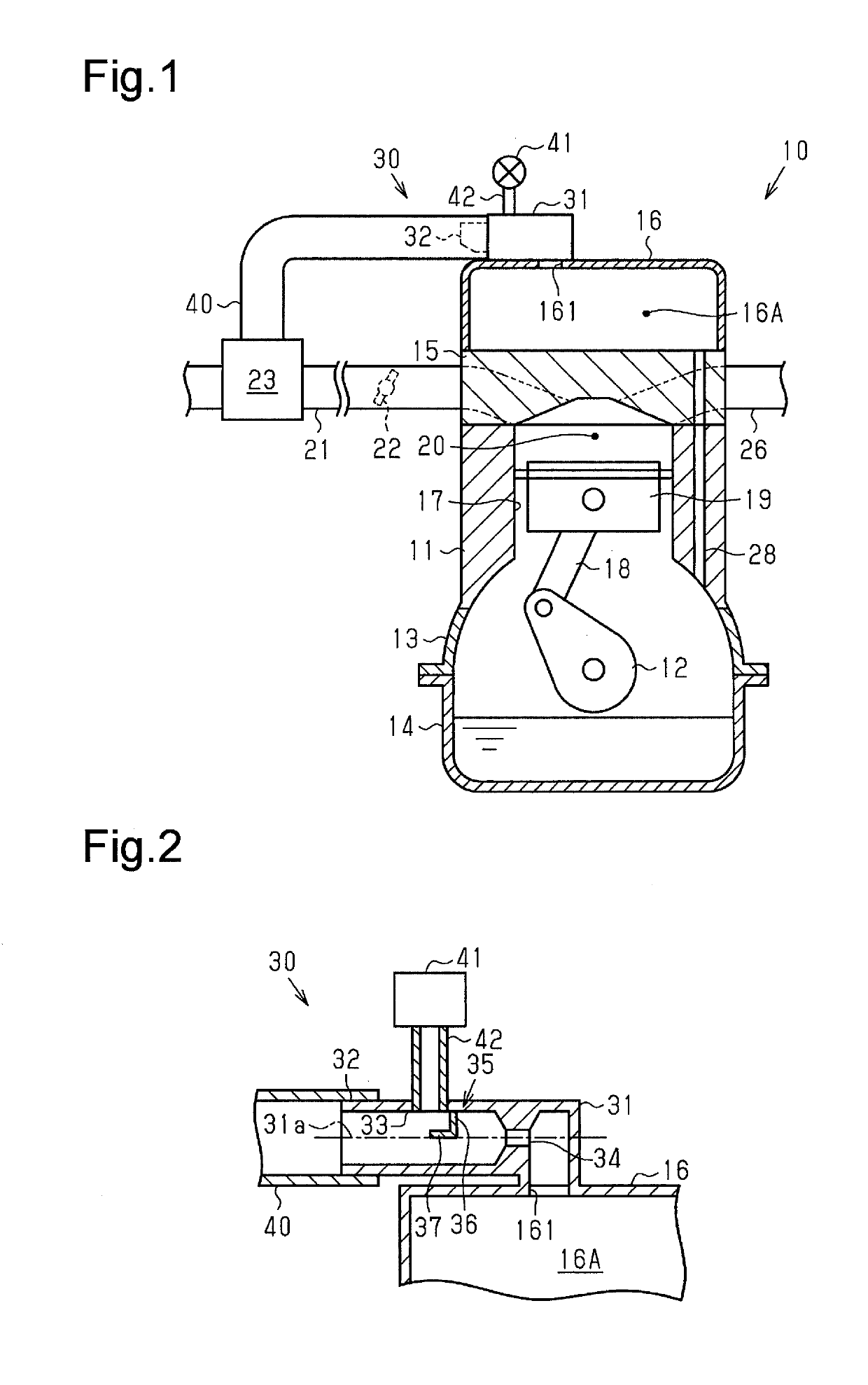
A blow-by gas treatment device causes blow-by gas in a space defined by a cylinder head and a head cover in an internal combustion engine to flow back into an intake pipe. The blow-by gas treatment device includes a pipe joint and a blow-by gas pipe connected to the intake pipe. The pipe joint includes a basal end connected to the head cover, a distal end, a sensor-connected part connected to the pressure sensor, and a constriction located closer to the basal end than the sensor-connected part. The blow-by gas pipe is connected to a position of the pipe joint closer to the distal end than the sensor-connected part.

Description

BACKGROUND1. Field[0001]The present disclosure relates to a blow-by gas treatment device for an internal combustion engine.2. Description of Related Art[0002]Blow-by gas that has leaked from the combustion chamber of an internal combustion engine into the crankcase flows through a communication passage extending across the cylinder block and the cylinder head into a space defined by the cylinder head and the head cover. Japanese Laid-Open Patent Publication No. 10-184336 describes a blow-by gas treatment device for an internal combustion engine that causes blow-by gas that has flowed into a head cover to flow back into an intake pipe through a blow-by gas passage connected to the head cover and the intake pipe.[0003]In the blow-by gas treatment device of the above-described document, the blow-by gas passage includes a blow-by gas valve. Further, a pressure sensor that detects the pressure in the blow-by gas passage is connected to a part of the blow-by gas passage between a portion ...

Claims


Application Information

Patent Timeline
Patent Type & Authority Applications(United States)
IPC IPC(8): F01M13/02F02M25/06F02M35/10
CPCF01M13/021F02M25/06F02M35/10222F02M35/1038F01M13/00F01M13/022F01M2013/0077F01M2013/0038F01M2013/0083F01M2250/00
Inventor ISHIKAWA, MASAMISHIBANUMA, SHIGERU
Owner TOYOTA JIDOSHA KK
Why Eureka
Try Eureka