Abnormality detection device and abnormality detection method
a technology of abnormality detection and detection method, which is applied in the field of abnormality detection devices and abnormality detection methods, can solve the problem of not being able to detect a single vehicle-mounted camera from its installed state, and achieve the effect of detecting the misalignment of the camera from the installed sta
- Summary
- Abstract
- Description
- Claims
- Application Information
AI Technical Summary
Benefits of technology
Problems solved by technology
Method used
Image
Examples
first modified example
5-1. First Modified Example
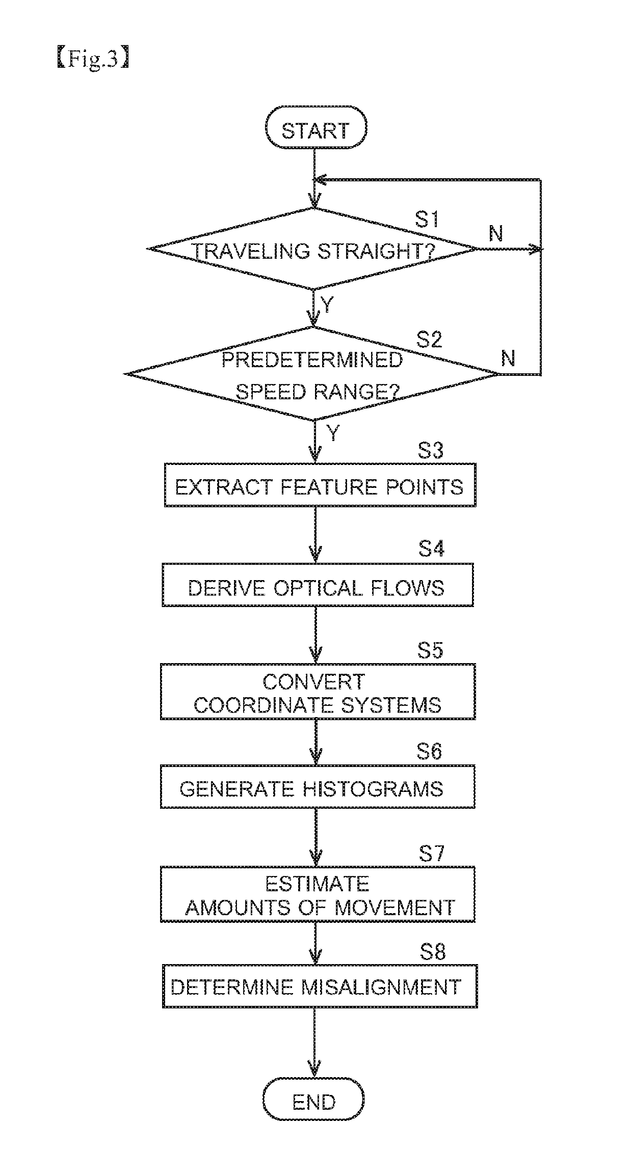
[0115]The above description deals with a configuration where, when the determiner 123 only once determines that a camera misalignment has occurred, the determination that a camera misalignment has occurred is taken as definitive, and thereby a camera misalignment is detected. This, however, is not meant as any limitation. Instead, when the determiner 123 determines that a camera misalignment has occurred, re-determination is performed at least once again so that, if it is once again determined that a camera misalignment has occurred, the determination that a camera misalignment has occurred is taken as definitive. The re-determination can be achieved with a configuration where steps S1 to S8 shown in FIG. 3 are simply repeated at least once again, or can be achieved with any other configuration. Re-determination can be applied to a procedure additionally involving the processing shown in FIGS. 16 and 17 for detecting the abnormal-estimation state.
[0116]FIG...
second modified example
5-2. Second Modified Example
[0119]FIG. 20 is a flow chart showing a modified example of the procedure for camera misalignment detection by the camera misalignment detecting device 1. The processing at steps S1 through S7 is the same as the above-described processing shown in FIG. 3, and therefore no description will be repeated. In this modified example, after the estimated values of the amounts of movement are calculated at step S7, processing for adding the calculated estimated values to the cumulative values of previously calculated amounts of movement is performed (step S9). This processing can be performed, for example, by the estimator 122 or the determiner 123. The cumulative value calculation processing is performed for each of the estimated value of the amount of movement in the front-rear direction and the estimated value of the amount of movement in the left-right direction. When estimated values are calculated for the first time, there is no previously calculated cumulat...
third modified example
5-3. Third Modified Example
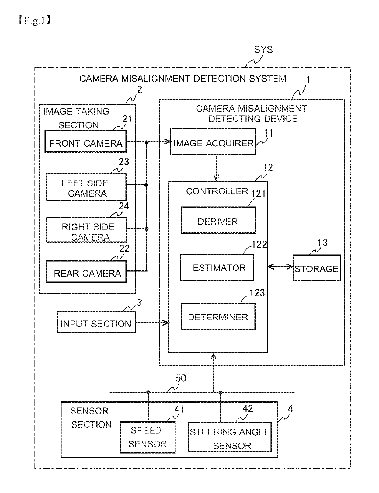
[0123]In what has been described thus far, the determiner 123 determines a camera misalignment based on the amounts of movement estimated from optical flows and the actually observed information obtained from a sensor such as the speed sensor 41. In the third modified example, the determiner 123 determines a camera misalignment, that is, an abnormality, through comparison among the amounts of movement estimated from optical flows in the vehicle-mounted cameras 21 to 24 respectively. In the third modified example, the estimator 122 estimates, based on images taken by the vehicle-mounted cameras 21 to 24 respectively, the amounts of movement of the mobile body for each of the plurality of cameras. The determiner 123 compares information on the amounts of movement for each of the cameras that is obtained in the estimator 122, and determines a camera in which the abnormality is occurring. For example, if the differences between the amounts of movement estimate...
PUM
 Abstract
Description
Claims
Application Information
 - R&D
- Intellectual Property
- Life Sciences
- Materials
- Tech Scout
- Unparalleled Data Quality
- Higher Quality Content
- 60% Fewer Hallucinations
Browse by: Latest US Patents, China's latest patents, Technical Efficacy Thesaurus, Application Domain, Technology Topic, Popular Technical Reports.
© 2025 PatSnap. All rights reserved.Legal|Privacy policy|Modern Slavery Act Transparency Statement|Sitemap|About US| Contact US: help@patsnap.com


