Oil air supply system

a technology of oil air supply system and oil, which is applied in the direction of engine components, mechanical equipment, distribution equipment, etc., can solve the problems of increased cost, difficult constant and stable detection, and terms of workability, so as to reduce cost, maintain detection accuracy, and accurately measure the change in flow rate

Inactive Publication Date: 2019-06-27
OKUMA CORP
View PDF0 Cites 0 Cited by
  • Summary
  • Abstract
  • Description
  • Claims
  • Application Information

AI Technical Summary

Benefits of technology

The invention provides an oil air supply system that can detect abnormal supply of oil air to multiple lubricating points with a simple and cost-effective design. The system uses a flow rate sensor in the lubricant oil supply pipeline to measure the flow rate of the oil and detect any abnormality in the supply. The system also includes a pressure sensor in the compressed air supply pipeline to detect any abnormality in the supply of the oil air. This ensures reliable and efficient delivery of oil air to multiple lubricating points.

Problems solved by technology

However, in the case of the oil air supply system described in JP-A-2006-258263, it is necessary to install a flow rate sensor in each of the plurality of oil air supply pipelines connecting the mixing device and the plurality of lubricating points, and thus there has been a problem of increased cost.
Further, in the aforementioned system, the flow rate sensor installed in each oil air supply pipeline is an optical sensor which detects the flow rate of oil particles, and thus it is difficult to constantly perform stable detections due to contamination or deterioration in the oil air supply pipelines.
In order to maintain detection accuracy, it becomes necessary to frequently perform maintenance or replacement of the oil air supply pipelines, and there has also been a problem in terms of workability.
Moreover, in the aforementioned system, the amount of lubricant oil distributed by the mixing device and flowing together with compressed air in each oil air supply pipeline is very small, and there has been a problem that it is extremely difficult to detect an abnormality by detecting an extremely minute change in the minute flow rate by the flow rate sensor.

Method used


Image

  • Oil air supply system

Examples


Embodiment Construction

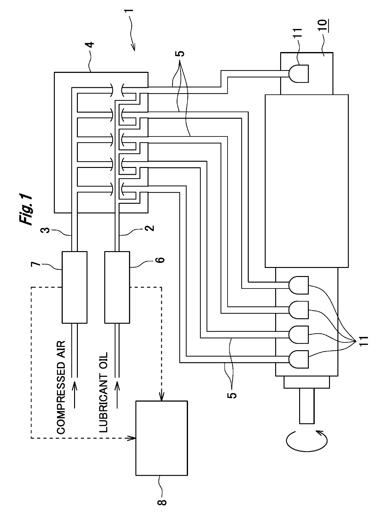
[0024]Hereinafter, the oil air supply system according to an embodiment of the invention will be described in detail with reference to FIG. 1.

[0025]In this embodiment, the invention is applied to an oil air supply system in a main spindle device of a machine tool.

[0026]As shown in FIG. 1, an oil air supply system (1) includes a lubricant oil supply pipeline (2), a compressed air supply pipeline (3), a mixing device (4) which distributes lubricant oil supplied from the lubricant oil supply pipeline (2) in a fixed amount and mixes the lubricant oil with compressed air supplied from the compressed air supply pipeline (3) to generate oil air, a plurality (five in this case) of oil air supply pipelines (5) which supply the oil air to a plurality (five in this case) of bearings (lubricating points) (11) of a main spindle device (10) respectively, a flow rate sensor (6) which is provided in the lubricant oil supply pipeline (2) and detects the flow rate of the lubricant oil, a pressure sen...


PUM


Abstract

The oil air supply system includes a lubricant oil supply pipeline, a compressed air supply pipeline, a mixing device which distributes lubricant oil supplied from the lubricant oil supply pipeline in a fixed amount and mixes the lubricant oil with compressed air to generate oil air, a plurality of oil air supply pipelines which supply the oil air to a plurality of bearings of a main spindle device respectively, a flow rate sensor provided in the lubricant oil supply pipeline and detects the flow rate of the lubricant oil, a pressure sensor provided in the compressed air supply pipeline and detects the pressure of the compressed air, and an abnormality detection device which detects supply abnormality of lubricant oil based on a detection signal output from the flow rate sensor and detects supply abnormality of compressed air based on a detection signal output from the pressure sensor.

Description

BACKGROUND OF THE INVENTIONField of the Invention[0001]The present invention relates to an oil air supply system for supplying oil air generated by mixing lubricant oil and compressed air to a plurality of lubricating points such as bearings in, for example, a main spindle device of a machine tool, etc.Background Art[0002]For example, oil air lubrication is widely used as a lubricating measure for bearings and the like in amain spindle device of a machine tool in which high speed and high accuracy are required.[0003]Here, as an oil air supply system used in oil air lubrication, there has been known an oil air supply system which supplies lubricant oil and compressed air to a mixing device, distributes lubricant oil in a fixed amount and mixes the lubricant oil with the compressed air to generate oil air in the mixing device, and distributes and supplies the generated oil air to a plurality of lubricating points such as bearings.[0004]In such an oil air supply system, when the supply...

Claims


Application Information

Patent Timeline
IPC IPC(8): F16N29/04F16N25/00F16N7/30
CPCF16N29/04F16N25/00F16N7/30F16N2210/14F16N2210/26F16N2250/04F16N2250/40F16N7/32F16N2260/05F16N2260/08
Inventor MIZUNO, SATOSHI
Owner OKUMA CORP
Why Eureka
Try Eureka