Control device for internal combustion engine and control method for internal combustion engine

a control device and internal combustion engine technology, applied in the direction of electric control, machines/engines, mechanical equipment, etc., can solve the problems of imbalance abnormality greater than actual degree, erroneous determination, etc., and achieve the effect of suppressing erroneous determination

Active Publication Date: 2019-06-27
TOYOTA JIDOSHA KK
View PDF10 Cites 2 Cited by
  • Summary
  • Abstract
  • Description
  • Claims
  • Application Information

AI Technical Summary

Benefits of technology

[0006]According to the first aspect of the present disclosure, determination is made that the degree of imbalance abnormality is smaller when the EGR rate is relatively small than when the EGR rate is relatively large even though the fluctuation amount of the detection value of the air-fuel ratio sensor is the same. For this reason, it is possible to determine the degree of imbalance abnormality taking into consideration that the fluctuation amount of the detection value of the air-fuel ratio sensor is greater when the EGR rate is relatively small than when the EGR rate is relatively large even though the degree of imbalance abnormality is the same. Accordingly, it is possible to suppress erroneous determination that the degree of imbalance abnormality is greater than actual, such as erroneous determination that an imbalance abnormality occurs when no imbalance abnormality actually occurs.

Problems solved by technology

That is, erroneous determination may be made that a degree of imbalance abnormality is greater than actual.

Method used


Image

  • Control device for internal combustion engine and control method for internal combustion engine
  • Control device for internal combustion engine and control method for internal combustion engine
  • Control device for internal combustion engine and control method for internal combustion engine

Examples


first embodiment

[0019]Hereinafter, a first embodiment of a control device for an internal combustion engine will be described referring to the drawings.

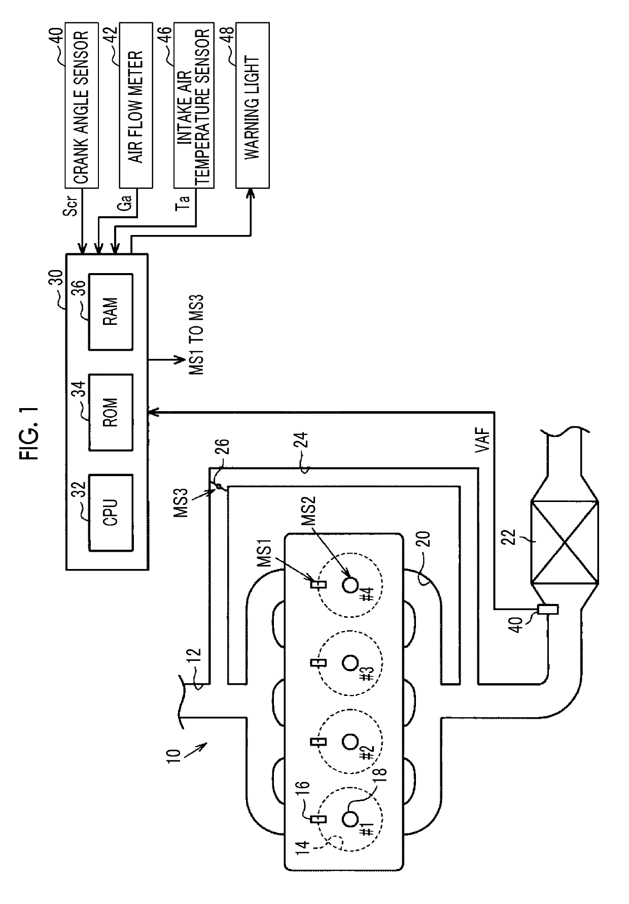
[0020]An internal combustion engine 10 shown in FIG. 1 is mounted in a vehicle. In the internal combustion engine 10, air sucked from an intake passage 12 flows into a combustion chamber 14 of each cylinder. Each of cylinders #1 to #4 are provided with a fuel injection valve 16 that injects fuel, and an ignition device 18 that causes spark discharge. In the combustion chamber 14, an air-fuel mixture of air and fuel is supplied for combustion, and the air-fuel mixture supplied for combustion is discharged as exhaust gas to the exhaust passage 20. The exhaust passage 20 is provided with a three-way catalyst 22 having an oxygen storage ability.

[0021]The exhaust passage 20 and the intake passage 12 are connected through an EGR passage 24, and the EGR passage 24 is provided with an EGR valve 26 that adjusts a flow passage cross-sectional area of the EGR ...

second embodiment

[0041]Hereinafter, a second embodiment will be described referring to the drawings while focusing on the difference from the first embodiment.

[0042]FIG. 9 shows a procedure of imbalance abnormality diagnosis processing M12 according to the embodiment. The processing shown in FIG. 9 is realized by the CPU 32 executing the program stored in the ROM 34 repeatedly in a predetermined cycle, for example. In FIG. 9, the processing corresponding to the processing shown in FIG. 4 is represented by the same step number for convenience.

[0043]In a sequence of processing shown in FIG. 9, when the processing of S12 is completed, the CPU 32 determines whether or not the opening degree command value θ* is zero (S18). When determination is made that the opening degree command value θ* is zero (S18: YES), the CPU 32 calculates a decrease correction coefficient Kn based on the rotation speed NE and the load factor KL (S20a). The decrease correction coefficient Kn is a parameter for decreasing and corr...


PUM


Abstract

A control device for an internal combustion engine is disclosed. The internal combustion engine includes a plurality of cylinders, a fuel injection valve configured to supply fuel to each cylinder, an EGR passage configured to connect an exhaust passage and an intake passage, an EGR valve configured to adjust a flow rate of exhaust gas flowing from the exhaust passage into the intake passage through the EGR passage, and an air-fuel ratio sensor provided in the exhaust passage. The control device includes an electronic control unit configured to execute determination processing for determining that a degree of imbalance abnormality is greater when a fluctuation amount of a detection value of the air-fuel ratio sensor is relatively large than when the fluctuation amount is relatively small.

Description

INCORPORATION BY REFERENCE[0001]The disclosure of Japanese Patent Application No. 2017-251355 filed on Dec. 27, 2017 including the specification, drawings and abstract is incorporated herein by reference in its entirety.BACKGROUND1. Technical Field[0002]The present disclosure relates to a control device for an internal combustion engine and a control method for an internal combustion engine that are applied to an internal combustion engine including a plurality of cylinders, a fuel injection valve configured to supply fuel to each cylinder, an exhaust gas recirculation (EGR) passage configured to connect an exhaust passage and an intake passage, an EGR valve configured to adjust a flow rate of exhaust gas flowing from the exhaust passage into the intake passage through the EGR passage, and an air-fuel ratio sensor provided in the exhaust passage.2. Description of Related Art[0003]Japanese Unexamined Patent Application Publication No. 2011-226363 (JP 2011-226363 A) discloses a contro...

Claims


Application Information

Patent Timeline
Patent Type & Authority Applications(United States)
IPC IPC(8): F02M26/49F02D41/00F02D41/14F02M26/42
CPCF02M26/49F02D41/0077F02D41/1454F02M26/42F02D2200/04F02D2200/101F02D41/0052F02D41/0085F02D41/1456F02D2041/228Y02T10/40
Inventor NAGAKURA, KEISUKEYAMADA, EIJI
Owner TOYOTA JIDOSHA KK
Why Eureka
Try Eureka