Fixing device and image forming apparatus
An image and ring-shaped technology, which is applied to the electrical recording process using charge graphics, equipment and instruments using the electrical recording process using charge graphics, can solve the problem of easy deformation of the heating rotating belt, and achieve the effect of suppressing misjudgment
- Summary
- Abstract
- Description
- Claims
- Application Information
AI Technical Summary
Problems solved by technology
Method used
Image

Examples
Embodiment approach 1
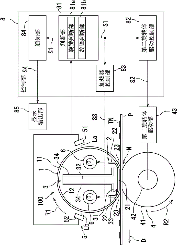
[0021] refer to figure 1 , Embodiment 1 of the fixing device 100 according to the present invention will be described. figure 1 It is a block diagram showing the functions of the fixing device 100 according to Embodiment 1 of the present invention.
[0022] The fixing device 100 includes a first rotating body 1 , a second rotating body 4 , two heaters 6 , a pressure receiving member 2 , a supporting member 3 , a position detection unit 5 , and a control unit 8 . For example, the fixing device 100 is installed in an image forming device. The fixing device 100 heats and pressurizes the recording medium P to fuse the unfixed toner TN on the recording medium P.
[0023] The first rotating body 1 is a cylindrical heating rotating belt. The first rotating body 1 is formed in a roll shape (an endless belt shape) and has heat resistance. The first rotating body 1 is rotatable in the circumferential direction (rotation direction R1 ) around a rotation axis extending in a direction ...
Embodiment approach 2
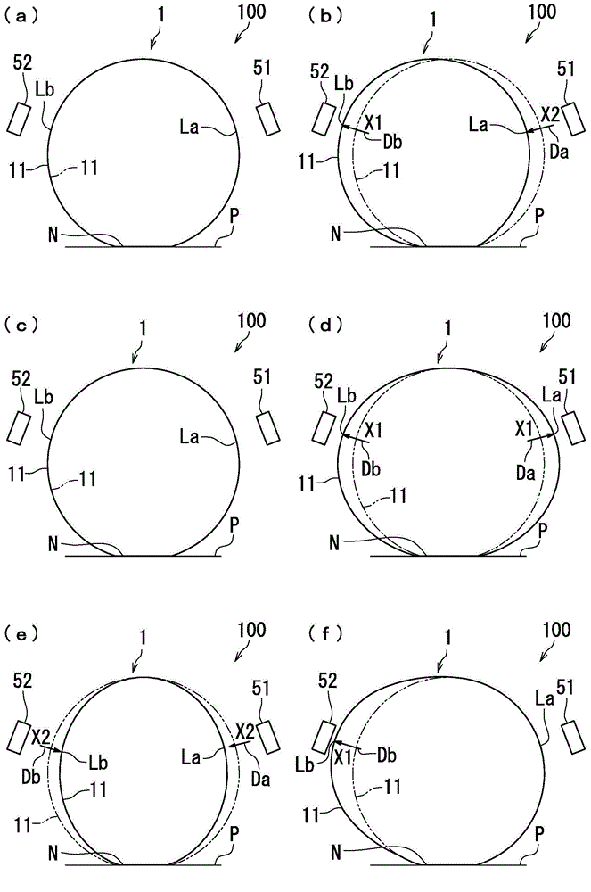
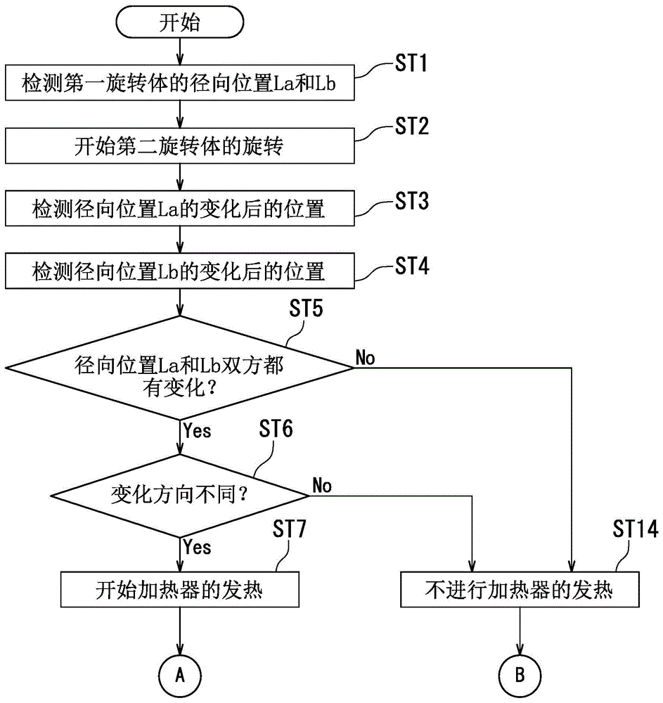
[0039] refer to Figure 1 ~ Figure 4 , Embodiment 2 of the fixing device 100 according to the present invention will be described. figure 2 (a)~ figure 2 (f) is a schematic side view showing the first rotating body 1 . exist figure 2 (a)~ figure 2 In (f), the second rotating body 4 , the heater 6 , the pressure receiving member 2 , the supporting member 3 , and the toner TN are omitted in order to avoid excessively complicated illustration. In the second embodiment, the judging unit 81 described in the first embodiment judges the rotation state of the first rotating body 1 according to the difference in the changing directions of the radial positions La and Lb.
[0040] The judging part 81 judges the rotation state of the first rotating body 1 according to the difference between the changing direction Da of the radial position La and the changing direction Db of the radial position Lb. The "direction of change" of the radial position relative to the reference position...
Embodiment approach 3
[0070] refer to figure 1 , Figure 5 (a)~ Figure 7 , the third embodiment of the fixing device 100 of the present invention will be described. Figure 5 (a)~ Figure 5 (d) is a schematic side view showing the first rotating body 1 . and figure 2 (a)~ figure 2 (f) Similarly, in Figure 5 (a)~ Figure 5 In (d), the second rotating body 4 , the heater 6 , the pressure receiving member 2 , the supporting member 3 and the toner TN are omitted. The difference is that, compared with the determination unit 81 described in the second embodiment, the determination is made according to the direction of change, while the determination unit 81 in the third embodiment is based on the sum of the changes in the radial positions La and Lb.
[0071] The judging unit 81 judges the rotation state based on the sum of the change Qa of the radial position La detected by the first position detecting member 51 and the change Qb of the radial position Lb detected by the second position detec...
PUM
 Abstract
Description
Claims
Application Information
 - R&D
- Intellectual Property
- Life Sciences
- Materials
- Tech Scout
- Unparalleled Data Quality
- Higher Quality Content
- 60% Fewer Hallucinations
Browse by: Latest US Patents, China's latest patents, Technical Efficacy Thesaurus, Application Domain, Technology Topic, Popular Technical Reports.
© 2025 PatSnap. All rights reserved.Legal|Privacy policy|Modern Slavery Act Transparency Statement|Sitemap|About US| Contact US: help@patsnap.com