
Air flap apparatus having an air flap constituted at least in portions from electrically conductive plastic for electrical heating thereof

a technology of air flap and electrical heating, which is applied in the direction of ohmic-resistance heating, electrical apparatus, component optimization, etc., can solve the problems of complex and costly approach proposed by the document of species, unsatisfactory differences in the dimensions of a given air flap apparatus, and no longer performing the intended function of controlling or regulating a convective cooling air flow to a heat exchanger. , to achieve the effect of simple structur

Inactive Publication Date: 2019-06-20
ROECHLING AUTOMOTIVE SE & CO KG
View PDF0 Cites 2 Cited by
  • Summary
  • Abstract
  • Description
  • Claims
  • Application Information

AI Technical Summary

Benefits of technology

The present invention proposes an air flap apparatus that can be electrically heated at least in portions, with a simplified structure. The heating portion of the air flap is made of electrically conductive plastic, which enables economical and efficient manufacturing. The entire surface of the flap leaf can be heated in a single heating operation, even if only a portion of it is made of electrically conductive plastic. This simplifies the manufacturing process and allows for quicker deicing of the flap.

Problems solved by technology

Those ambient temperatures can fluctuate in the course of a year by several dozen kelvin depending on the operating region of the motor vehicle; depending on the season and on the coefficient of thermal expansion of the material or materials used to constitute the air flap apparatus, this can result in undesired differences in the dimensions of a given air flap apparatus.
Regardless of the respective temperature differences occurring in the course of a year between a maximum and minimum temperature, the air flap apparatus can be immobilized by icing if the temperature falls below the freezing point, and can thus no longer perform its intended function of controlling or regulating a convectively cooling air flow to a heat exchanger of an internal combustion engine.
The approach proposed by the document of the species is, however, complex and costly.

Method used


Image

  • Air flap apparatus having an air flap constituted at least in portions from electrically conductive plastic for electrical heating thereof
  • Air flap apparatus having an air flap constituted at least in portions from electrically conductive plastic for electrical heating thereof
  • Air flap apparatus having an air flap constituted at least in portions from electrically conductive plastic for electrical heating thereof

Examples


Embodiment Construction

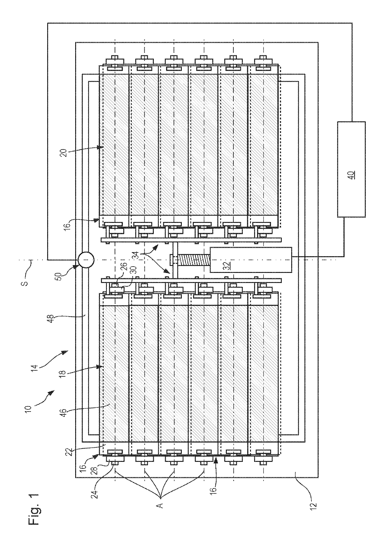
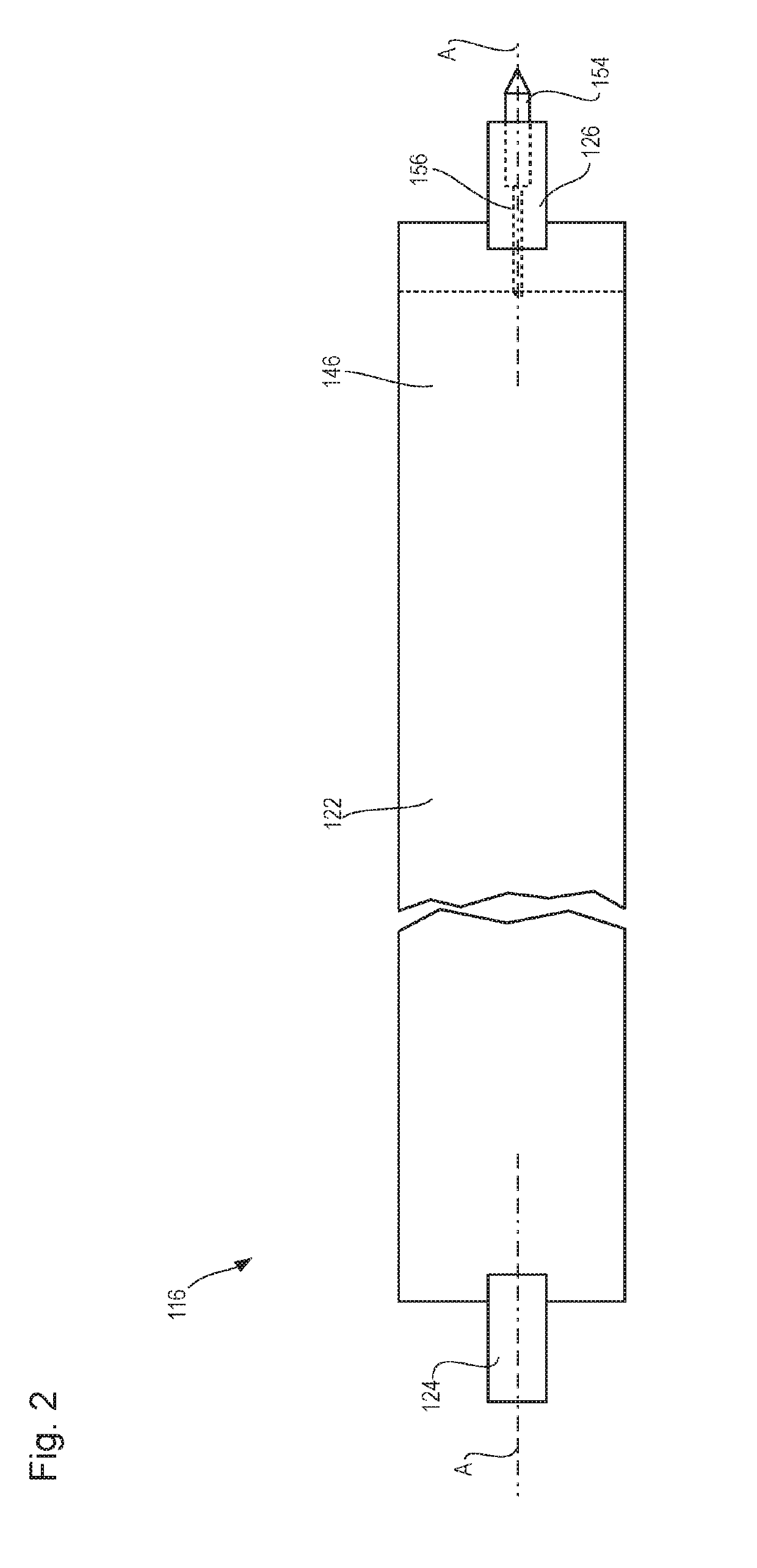
[0033]Referring now to the drawing wherein the showings are for the purpose of illustrating preferred and alternative embodiments of the invention only and not for the purpose of limiting the same, FIG. 1 shows an embodiment according to the present invention of an air flap apparatus of the present Application, depicted in a schematic rear view, that is designated generally as 10. Air flap apparatus10 encompasses an apparatus frame 12 that defines a passthrough opening 14 and that movably supports a plurality of air flaps 16. Passthrough opening 14 is divided into two partial passthrough openings 18 and 20 through each of which air flaps 16 pass.

[0034]Air flaps 16 of left partial passthrough opening 18 and of right partial passthrough opening 20 are embodied mirror-symmetrically with reference to a mirror symmetry plane S that is orthogonal to the drawing plane of FIG. 1 and is located equidistantly from the two partial passthrough openings 18 and 20. Given the mirror symmetry, it i...


PUM


Abstract

An air flap apparatus for a motor vehicle encompasses an apparatus frame having a passthrough opening and having at least one air flap, received on the frame movably between an open position and a closed position, for modifying an air flowthrough-capable cross section of the passthrough opening, the flowthrough-capable cross section of the passthrough opening being larger when the at least one air flap is in the open position than when the at least one air flap is in the closed position, a selectably current-passage-capable electrical resistance heating apparatus, which encompasses a heating conductor and a current source, being provided in the at least one air flap, the current source being embodied to output to the heating conductor an electrical power level that is sufficient to heat it from an initial temperature of 20° C. by at least 2 K in 10 minutes, at least one heating portion of the at least one air flap is constituted from electrically conductive plastic, so that the air flap itself constitutes the heating conductor.

Description

[0001]The present invention relates to an air flap apparatus for a motor vehicle. The air flap apparatus encompasses an apparatus frame having a passthrough opening and having at least one air flap, received on the frame movably between an open position and a closed position, for modifying the size of an air flowthrough-capable cross section of the passthrough opening. The flowthrough-capable cross section of the passthrough opening is larger when the at least one air flap is in the open position than when the at least one air flap is in the closed position. A selectably current-passage-capable electrical resistance heating apparatus, which encompasses a heating conductor and a current source, is provided in the at least one air flap. The current source is embodied to output to the heating conductor an electrical power level that is sufficient to heat it from an initial temperature of 20° C. by at least 2 K in 10 minutes.BACKGROUND OF THE INVENTION[0002]An air flap apparatus of the ...

Claims


Application Information

Patent Timeline
IPC IPC(8): H05B3/26B60K11/08
CPCH05B3/26B60K11/08B60K11/085H05B3/267H05B2214/02Y02T10/88
Inventor TSIGKOPOULOS, THOMASPFAFFELHUBER, KLAUS
Owner ROECHLING AUTOMOTIVE SE & CO KG
Learn More