Offshore reservoir monitoring system and method for its operation

a reservoir monitoring and monitoring system technology, applied in the field of active and/or passive seismic monitoring, can solve the problems of only being able to remove interface waves, contaminating seismic data acquired by most seabed sensors, and not being able to bury sensors away from interface waves, etc., to achieve the effect of saving storage space, less equipment, and shortening the tim

Inactive Publication Date: 2019-06-20
SOUNDSABRE
View PDF0 Cites 5 Cited by
  • Summary
  • Abstract
  • Description
  • Claims
  • Application Information

AI Technical Summary

Benefits of technology

[0036]Recording data may involve signal processing at the recording node. The main advantage is to save storage space, especially during microseismic monitoring.
[0037]Specifically, recording data may involve deriving one or more vector gradients of one or more wavefields for signals coming from a variety of vertical and non-vertical angles. This can be done using differential vector phase shifts as mentioned above, and allows double spatial frequencies to be estimated. In this way, the source or receiver spacing can be twice what they are for a conventional seafloor array without loss of image quality. Thus, the monitoring survey can be performed with less equipment and in a shorter time, both of which reduce the cost of a survey. Alternatively, the image quality may improve significantly without a corresponding raise in survey costs.

Problems solved by technology

However, it may not be possible or desirable to bury the sensors away from interface waves.
In these cases, the interface waves can only be removed by sampling and wave reconstruction currently unavailable from most recording systems.
Thus, Scholte waves and related phenomena contaminate seismic data acquired by most seabed sensors.
However, towed streamer 4D suffers from low repeatability and long times between reshoots, typically 2-10 years, which limits its applicability to fields with a strong time-lapse signature and slow reservoir changes.
In addition, towed streamers do not record S-waves as shear waves do not propagate through water.
In some instances, e.g. to reduce exploration costs, the distance between shots is too coarse for proper sampling of the body wavefields.
This article also suggests a seabed cube of sensors, which most likely would be too expensive and impractical for commercial use.
The use of PRM-systems has grown gradually over the last decade but they are relatively expensive to install and usually require more than five years to plan, fund and execute.
These systems need to be connected to fixed infrastructure which adds to the cost and makes them inflexible and non-scalable as a small array can cost almost as much as a large one.
In addition, the single sensor locations are still affected by noise trapped in the water column and from interface waves at the seafloor.
They also have problems with coupling between the sensors.
Such distances are too large to provide the sampling required for effective removal of interface waves at the seafloor.
In addition, water currents generate noise by causing nodes and cables on the seafloor to vibrate.
Finally, the sensitivity of seafloor nodes for passive monitoring is low due to poor mechanical coupling to the seabed, high levels of noise, and often strong absorption in the very shallow layers.
At present, there are few or no dedicated products available for passive monitoring offshore.
PRM systems are designed for active surveys and since they are located very near the surface they are still affected by noise generated by the irregularity of the seabed, by noise from other sources which propagates along the seabed and diminished signals caused by the long distance from the source.
Stand-alone monitoring nodes placed on the surface have been shown to be even more susceptible to surface noise and so ineffective for all but the strongest microseismic signals.
Well based monitoring is the most effective for localised microseismic monitoring but is also by far the most expensive.
Deployment in production and injection wells is rarely approved due to the extra risk of completion failure and deployment in a dedicated monitoring well is still too expensive for many applications.
DAS-sensors rely on Rayleigh backscattering, and are currently too insensitive for effective monitoring of the weak microseismic signals.

Method used


Image

  • Offshore reservoir monitoring system and method for its operation
  • Offshore reservoir monitoring system and method for its operation
  • Offshore reservoir monitoring system and method for its operation

Examples


Embodiment Construction

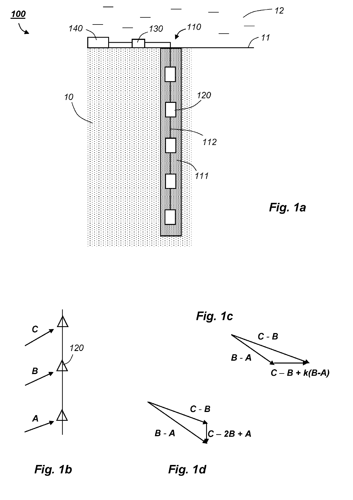
[0046]The drawings are schematic and not to scale. For ease of understanding, numerous details known to the skilled person are omitted from the drawings and following description.

[0047]The problem at hand may loosely be described as measuring a property u(x, t)=(u(t), v(t), w(t)) at discrete points (X, Y, Z, t) in space and time. A formal discussion of known representations of the seismic equations is beyond the scope of this disclosure. However, we note that the problem may be described as determining a boundary condition or final state, hereinafter a “wavefield” for short, sampled at discrete points (X, Y, Z, t) in space-time. Hence, the Nyquist-Shannon sampling theorem is central to ensure proper reconstruction of the full wavefield in spatial and temporal directions, and appears in some examples below.

[0048]The focal point mechanism describes the nature of a microseismic event, e.g. a dip slip, strike slip, dilation or a combination, and is typically derived from observation of ...


PUM


Abstract

An offshore reservoir monitoring system (100) comprises a vertical array (110) with multiple seismic receivers (120) less than 10 m apart. During operation, the vertical array is deployed in a shallow borehole (111) in a seabed (10) away from noise at a seafloor (11). The dense spacing of receivers (120) ensures an adequate number of sensors (120) in the shallow borehole (111) and a spatial sampling rate appropriate for suppressing coherent noise in the shallow layers under the seafloor (11). Vertical arrays (110) can be added to the system (100) at any time.

Description

BACKGROUNDField of the Invention[0001]The present invention relates to active and / or passive seismic monitoring of a subsurface geologic formation under a body of water. Specifically, the invention concerns an offshore reservoir monitoring system and a method for its operation.Prior and Related Art[0002]In the following, an offshore reservoir is any multi-layered structure of sediments and rock under a body of water. The term “surface” will refer to the sea surface above the body of water, and the term “seafloor” means the interface between the body of water and a “seabed”. As used herein, the seabed is the upper layers of the Earth's crust, and may comprise sediments or solid rock.[0003]A reservoir may produce hydrocarbons through a production well and / or be used as a storage facility, e.g. for CO2. Monitoring a field has several aims, e.g. identifying a water front approaching a production well, characterising cracks developing during injection or monitoring natural seismicity.[00...

Claims


Application Information

Patent Timeline
Patent Type & Authority Applications(United States)
IPC IPC(8): G01V1/52G01V1/22
CPCG01V1/52G01V1/226G01V2210/1234G01V2210/3246G01V2210/1427G01V1/208G01V1/36G01V1/3808G01V1/42G01V2210/121G01V2210/1429G01V2210/56G01V2210/57
Inventor WATTS, GILES FRANCIS TANFIELDJACK, IAN GORDONVOLANTHEN, MARK
Owner SOUNDSABRE
Why Eureka
Try Eureka