
Two Stage Cooler

a cooler and two-stage technology, applied in indirect heat exchangers, lighting and heating apparatus, heating types, etc., can solve the problems of reducing the overall efficiency of cooling, reducing the and requiring significant energy to operate the compressor. the effect of increasing the amount of air drawn by the lower fan

Active Publication Date: 2019-06-20
OXYCOM BEHEER BV
View PDF4 Cites 1 Cited by
  • Summary
  • Abstract
  • Description
  • Claims
  • Application Information

AI Technical Summary

Benefits of technology

The patent describes an evaporative cooling device that uses a housing with multiple openings and fans to move air through the device. The device contains elements that help cool the air using evaporation, such as fibrous or plastic layers or finned plates made of aluminum material. The aluminum material helps transfer heat within the elements, optimizing heat exchange. The elements may also have a water retaining coating to help keep water within the structure of the elements. The technical effects of the patent are a compact, efficient, and effective evaporative cooling device that can be used in various applications.

Problems solved by technology

In cases where the wet bulb temperature of the air is above the desired temperature for a habitable space, such coolers may not be sufficient.
Compared to evaporative systems, air conditioning units require significant energy to operate their compressors.
This reduces the overall efficiency of the cooling and in order to have sufficient air for delivery, a considerable frontal area of the evaporative cooler is required.
Scaling up of such devices is not always practical.

Method used


Image

  • Two Stage Cooler
  • Two Stage Cooler
  • Two Stage Cooler

Examples


Embodiment Construction

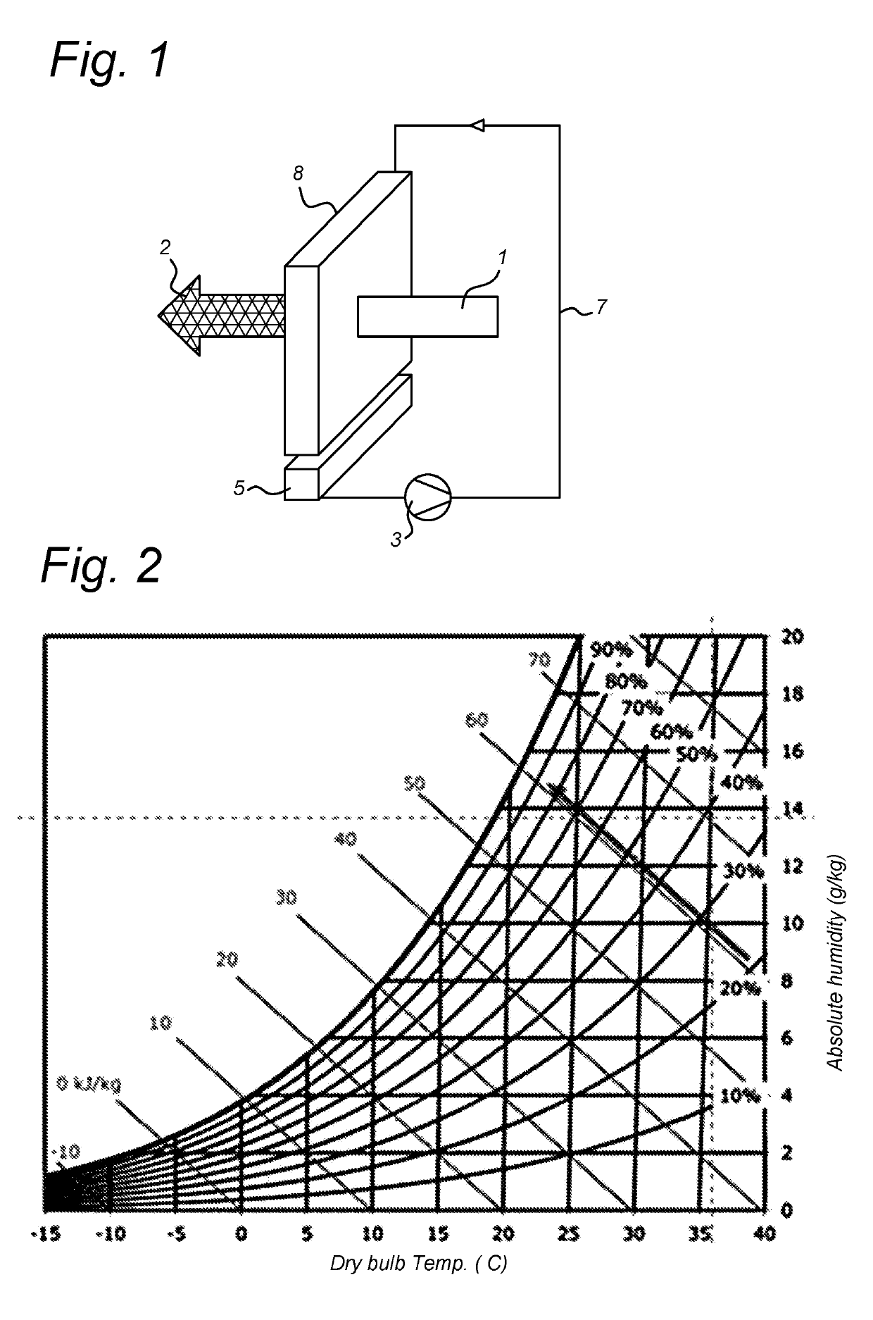
[0027]FIG. 1 shows a schematic view of operation of a conventional direct evaporative cooler such as the above mentioned Oxyvap™ pad described in WO2013095105. Hot dry air 1 is passed through the pad 8 to which water is supplied by water circuit 7 including pump 3 and sump 5. The air is humidified by the water as it passes through the pad 8 and exits as colder and more humid air 2 at the wet-bulb temperature (or close thereto). In FIG. 2, it may be seen that air having an initial dry-bulb temperature of 38° C. and 21% humidity can be cooled to around the wet bulb temperature of 21° C. In actual practice, 90% efficiency may be achieved and the outlet temperature may be around 1.7° C. higher than the wet-bulb temperature. Due to the cooling effect, the water exiting the pad 8 and collected in the sump 5 is also at the wet bulb temperature.

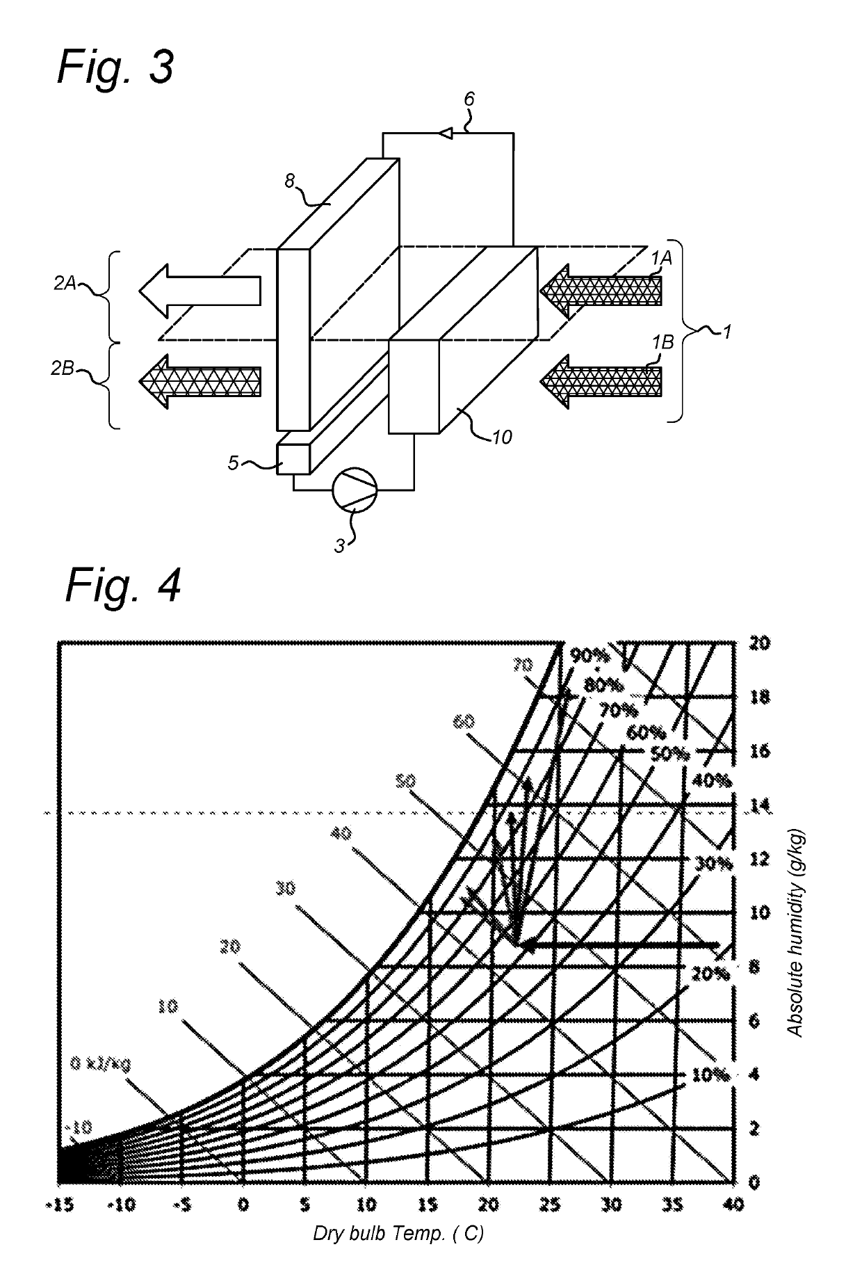
[0028]FIG. 3 shows an arrangement in which a pre-cooler 10 has been placed ahead of a lower portion of the Oxyvap pad 8 of FIG. 1. The cooled water ...


PUM


Abstract

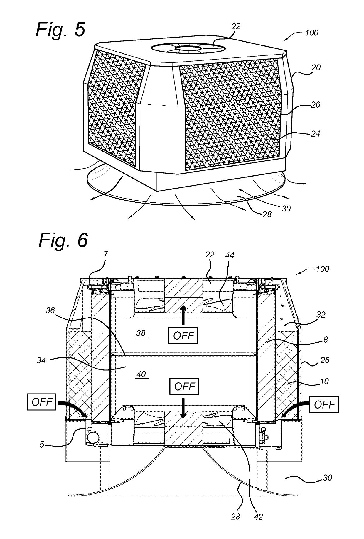
A two stage evaporative cooling device has a central chamber, divided into an upper chamber and a lower chamber by a divider. one or more heat exchange units surrounding the central chamber; an upper fan arranged above the upper chamber and a lower fan arranged below the lower chamber; and a water circuit; wherein each heat exchange unit comprises an evaporative cooling element and an air to water pre-cooler, the pre-cooler being placed ahead of a lower portion of the cooling element and the water circuit is arranged to irrigate the cooling element and collect the irrigated water below the cooling element for delivery to the pre-cooler whereby pre-cooled air may be drawn inwardly through the pre-cooler and the lower part of the cooling element by the lower fan and ambient air may be drawn inwardly through the upper part of the cooling element by the upper fan.

Description

BACKGROUND OF THE INVENTION1. Field of the Invention[0001]The present invention relates to an evaporative cooling device and more particularly to a compact direct evaporative cooler provided with precooling. The invention also relates to the use of such a device in providing a supply of cooling air.2. Description of the Related Art[0002]Evaporative cooling is well known as a method of providing a flow of cooling air. For air that is above its dew point, a reduction of the absolute temperature of the air can be achieved by the introduction of moisture. When this takes place directly into the air stream, the temperature of the air may be lowered as far as the wet bulb temperature. Such direct evaporative coolers, sometimes known as swamp coolers are very effective in hot dry climates. They are also highly efficient, since they require little more energy than for operation of a fan.[0003]In cases where the wet bulb temperature of the air is above the desired temperature for a habitable...

Claims


Application Information

Patent Timeline
Patent Type & Authority Applications(United States)
IPC IPC(8): F24F5/00F24F1/0087F24F1/0043
CPCF24F5/0035F24F1/0087F24F1/00073F28D5/00F24F1/0011F24F1/0007Y02B30/54F24F1/0043
Inventor REINDERS, JOHANNES ANTONIUS MARIAREINDERS, BEREND JANHAKBIJL, MARKBANZ, ALEXANDER JOHN
Owner OXYCOM BEHEER BV
Learn More