
Smart Internet High-Definition Scanner with Laser Correction

a high-definition scanner and laser correction technology, applied in the field of smart internet high-definition scanners with laser correction, can solve the problems of serious impact on subsequent ocr text recognition, serious bending, and serious affecting reading quality

Inactive Publication Date: 2019-06-13
DALIAN CHENGZHE TECH
View PDF0 Cites 7 Cited by
  • Summary
  • Abstract
  • Description
  • Claims
  • Application Information

AI Technical Summary

Benefits of technology

The present invention provides a smart Internet high-definition scanner with laser correction that can scan book pages quickly and accurately. The scanner includes a calibration laser emission unit, an image collection unit, and an image processing unit. The calibration laser emission unit emits a laser beam to the book page and forms a laser line on the surface of the page. The image collection unit collects a planar image of the bent page with the laser line and calculates the coordinates of each pixel point on the laser line in the planar image. The image processing unit analyzes the y coordinate of each pixel point on the laser line and obtains the actual space height of each pixel point. The scanner can also have a fixed mount for the laser emission device and a light supplementation unit. The invention allows for quick and accurate book scanning and improves the accuracy of laser correction.

Problems solved by technology

However, when such picture collection scanner scans a scanned object having a certain thickness, such as a dictionary or a textbook with a large thickness, a scanning image scanned in the page in the middle of the book may have a large degree of bending, which seriously affects the reading quality, and the bending can have a serious impact on subsequent OCR text recognition.

Method used


Image

  • Smart Internet High-Definition Scanner with Laser Correction
  • Smart Internet High-Definition Scanner with Laser Correction
  • Smart Internet High-Definition Scanner with Laser Correction

Examples


Embodiment Construction

[0035]In order to make the objects, the technical solutions and the advantages of the embodiments of the present invention clearer, the technical solutions in the embodiments of the present invention are clearly and completely described with reference to the drawings in the embodiments of the present invention.

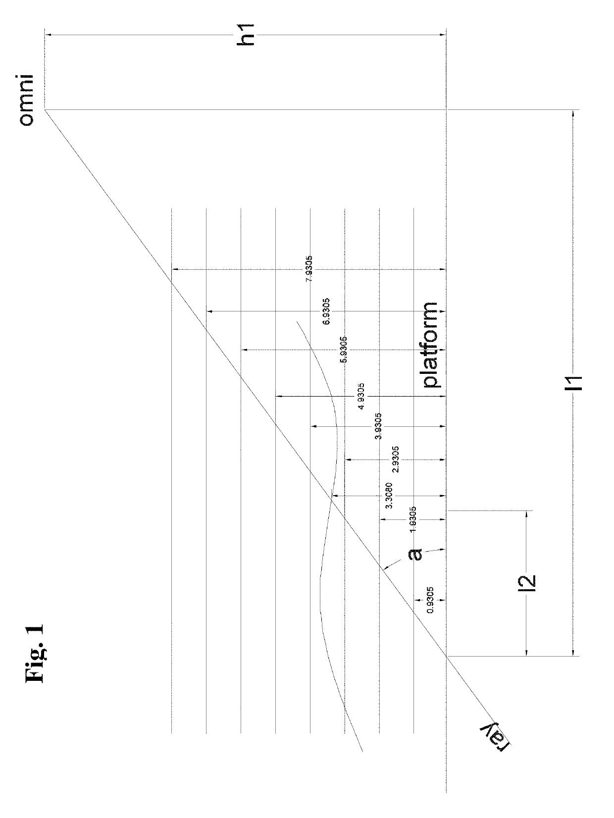
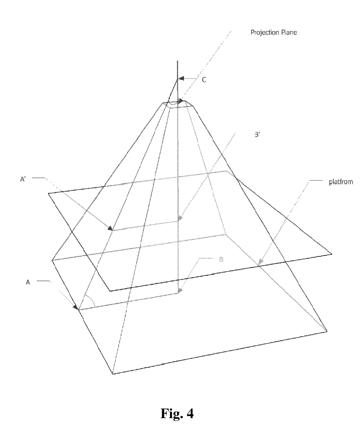
[0036]As shown in FIG. 1 to FIG. 6, a smart Internet high-definition scanner with laser correction mainly comprises a set scanning area and a scanner with an image collection camera.

[0037]A plane of a certain size bearing the scanner can be directly used as the scanning area, such as a desk surface or a work surface where the scanner is placed. A special support plate unfolded by a certain angle can also be used to better guarantee that, after a certain thickness of the pages of the book are opened, the pages are still kept in an opened state under the deadweight thereof, which can save an external force for pressing a thicker book.

[0038]Preferably, a planar scanning area is d...


PUM


Abstract

The present invention discloses a smart Internet high-definition scanner with laser correction, which comprises a scanning area for placing a book to be scanned; a calibration laser emission unit located above the scanning area, an image collection unit and an image processing unit; wherein the calibration laser emission unit emits a laser beam to the book unfolded and placed on the scanning area, and forms a laser line on a surface of an opened page; the image collection unit collects a planar image of the bent page with the laser line; by establishing a three-dimensional coordinate system, and according to coordinates of pixel points of the laser line and an intersection angle between the laser beam and a plane of the scanning area, height coordinates of each pixel point on the laser line in the planar image in the three-dimensional coordinate system is obtained through calculation, a 3D curve of the laser line in the three-dimensional coordinate system is restored, and a real 3D curved surface of the page in the three-dimensional coordinate system is constructed according to the 3D curve; and a correlation between points on the 3D curved surface and the pixel points in the planar image is obtained through calculation, and the 3D curved surface after pixel value replacing is straightened, to complete scanning the current page.

Description

TECHNICAL FIELD[0001]The present invention relates to a smart Internet high-definition scanner with laser correction. The present invention relates to IPC (International Patent Classification) H04 electric communication technique; H04N pictorial communication, e.g. television; H04N1 / 00 scanning, transmission or reproduction of document or the like, e.g. facsimile transmission, details thereof; H04N1 / 04 scanning arrangements; H04N1 / 10 using flat picture-bearing surfaces.BACKGROUND ART[0002]With the development of video collection and processing technology, the scanner has been upgraded from traditional light-sensitive scanner to a new generation of image collection scanner based primarily on video image collection. This new type of scanner collects a photo of a page through a camera located above the scanned object to complete scan, which eliminates the heavy workload caused by the traditional scanning method of manually pressing a presswork to be scanned on a scanning surface, so as...

Claims


Application Information

Patent Timeline
Patent Type & Authority Applications(United States)
IPC IPC(8): H04N1/00H04N1/10H04N1/028
CPCH04N1/00827H04N1/10H04N1/0282H04N1/00801H04N1/00328H04N1/04H04N1/1265H04N1/028H04N1/12
Inventor ZHOU, KANG
Owner DALIAN CHENGZHE TECH
Learn More