Laminar airfoil and the assembly and mounting of solar cell arrays on such airfoils

a solar array and airfoil technology, applied in the field of solar cells, can solve the problems of increasing the complexity of manufacturing, reducing the performance of the aircraft, and impracticality of placement, and achieves the effects of less drag or resistance, convenient assembly, and less drag or resistan

Active Publication Date: 2019-06-06
SOLAERO TECH CORP
View PDF4 Cites 2 Cited by
  • Summary
  • Abstract
  • Description
  • Claims
  • Application Information

AI Technical Summary

Benefits of technology

[0012]According to this aspect, a solar cell assembly is first arranged on a smooth planar surface of the assembly fixture, which facilitates the manufacture of the assembly. Afterwards, this same assembly may be removed from the assembly fixture and positioned on a streamlined body, e.g. a wing of an aircraft, or a portion of a watercraft or a land vehicle.
[0013]The solar cell assembly has a first tapering portion. When the solar cell assembly is positioned on the streamlined body, laminar air flow may be maintained around the streamlined body, since the air (or other fluid) flow does not encounter any bumps or sudden curvature changes, which can provoke a flow to become turbulent or can provoke flow separation. A laminar air flow around a body can lead to less drag or resistance, and can lead to more lift (in the case of e.g. an airfoil). A turbulent flow, or a wake (this occurs when a boundary layer become detached form a body, i.e. flow separation) can lead to a significant increase in drag, and potentially to a loss of lift. The thickness of the solar cell assembly in the area where the solar cells are arranged may be substantially constant.

Problems solved by technology

Compared to silicon, III-V compound semiconductor multijunction devices have greater energy conversion efficiencies and generally more radiation resistance, although they tend to be more complex to manufacture.
The placement of such solar cells, or encapsulated films incorporating such solar cells, on the surface of an airfoil results in a “step” or discontinuity of the surface of the airfoil which prevents the laminar flow of air over the airfoil surface, thereby substantially decreasing the aircraft's performance and making such placement as impractical.
There is a continuing need for improved methods of manufacturing and assembling photovoltaic solar arrays that can result in a smoother top surface that will permit laminar air flow there over, as well as decreases in cost and / or increases in performance.

Method used


Image

  • Laminar airfoil and the assembly and mounting of solar cell arrays on such airfoils
  • Laminar airfoil and the assembly and mounting of solar cell arrays on such airfoils
  • Laminar airfoil and the assembly and mounting of solar cell arrays on such airfoils

Examples


Embodiment Construction

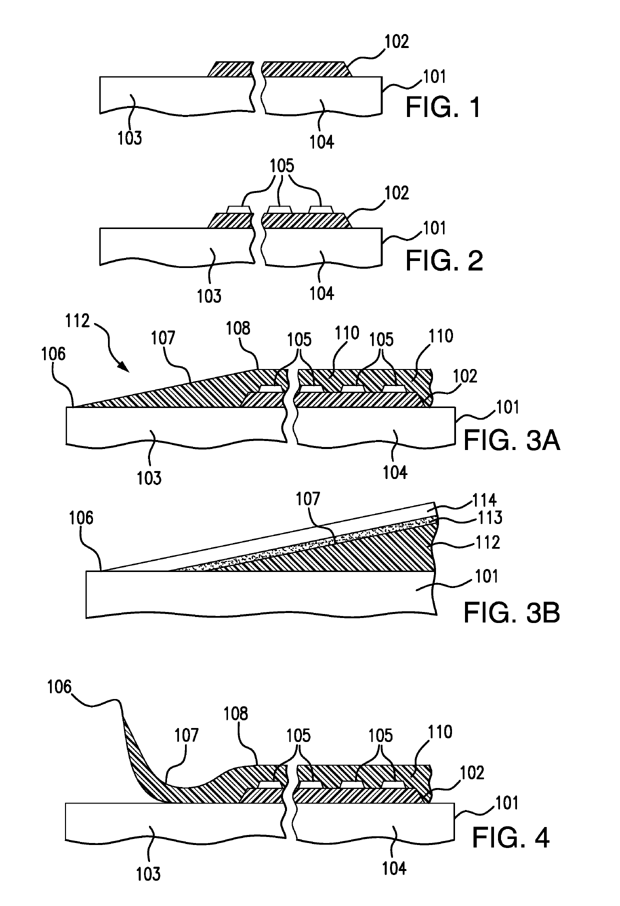
[0053]Details of the present invention will now be described including exemplary aspects and embodiments thereof. Referring to the drawings and the following description, like reference numbers are used to identify like or functionally similar elements, and are intended to illustrate major features of exemplary embodiments in a highly simplified diagrammatic manner. Moreover, the drawings are not intended to depict every feature of the actual embodiment nor the relative dimensions of the depicted elements, and are not drawn to scale.

[0054]FIG. 1 is a cross-sectional view of a generally planar fixture 101 for assembling the airfoil layer with a solar cell assembly according to the present disclosure after the first process step of depositing a first silicone supporting film 102 on a first portion 104 of the fixture.

[0055]FIG. 2 is a cross-sectional view of the fixture of FIG. 1 after the next process step of attaching the solar cell assembly including a plurality of interconnected so...


PUM


Abstract

Methods of fabricating a solar cell assembly for streamlined bodies are provided. The solar cell assembly may be prepared on an assembly fixture. The solar cell assembly may then be removed from the assembly fixture and positioned on a top surface of the streamlined body. In examples, the solar cell assembly comprises a first film, an array of solar cells on top of the first film, and a second silicone film deposited over the solar cells.

Description

REFERENCE TO RELATED APPLICATIONS[0001]This application is related to U.S. patent application Ser. No. 15 / 359,814 filed Nov. 23, 2016.BACKGROUND OF THE DISCLOSURE1. Field of the Disclosure[0002]The present disclosure relates to arrays of solar cells arranged on streamlined bodies of vehicles. The present disclosure particularly relates to the field of laminar airfoils, and photovoltaic solar arrays mounted on such airfoils, and more particularly to fabrication processes utilizing, for example, interconnected multijunction solar cells based on III-V semiconductor compounds mounted on a film and adhered to the airfoil structure while preserving its laminar surface.2. Description of the Related Art[0003]Solar power from photovoltaic cells, also called solar cells, has been predominantly provided by silicon semiconductor technology. In the past several years, however, high-volume manufacturing of III-V compound semiconductor multijunction solar cells for space applications has accelerat...

Claims


Application Information

Patent Timeline
Patent Type & Authority Applications(United States)
IPC IPC(8): H01L31/0203H02S20/30H01L31/042H01L31/18
CPCH01L31/0203H02S20/30H01L31/042H01L31/1876H01L31/1804B64D41/00B64D2211/00H01L31/1892Y02E10/547Y02T50/50B64D27/02
Inventor KRUSE, MATTHEWHERNANDEZ, FADEL
Owner SOLAERO TECH CORP
Why Eureka
Try Eureka