
Backlight Unit and Display Device

a backlight unit and display device technology, applied in non-linear optics, instruments, optics, etc., can solve the problems of lowering the uniformity of display brightness, insufficient light supply to a specific area of the display panel,

Active Publication Date: 2019-05-30
LG DISPLAY CO LTD
View PDF10 Cites 2 Cited by
  • Summary
  • Abstract
  • Description
  • Claims
  • Application Information

AI Technical Summary

Benefits of technology

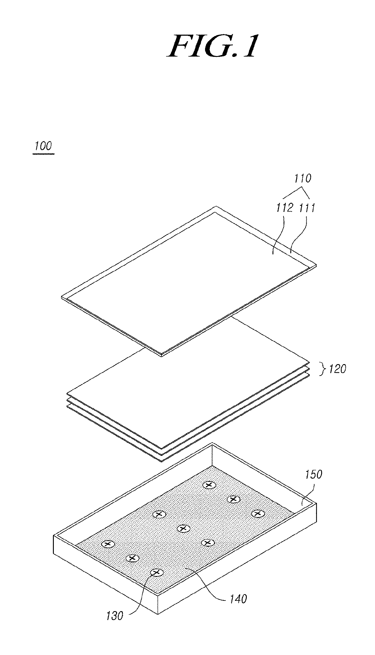
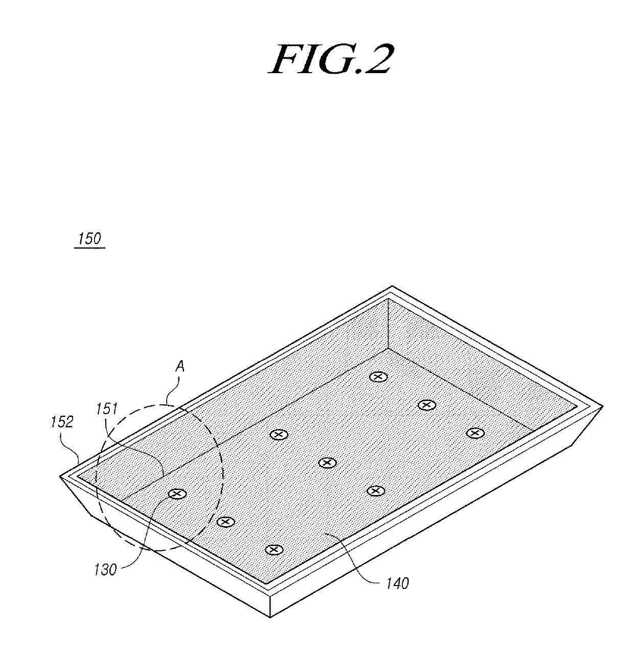
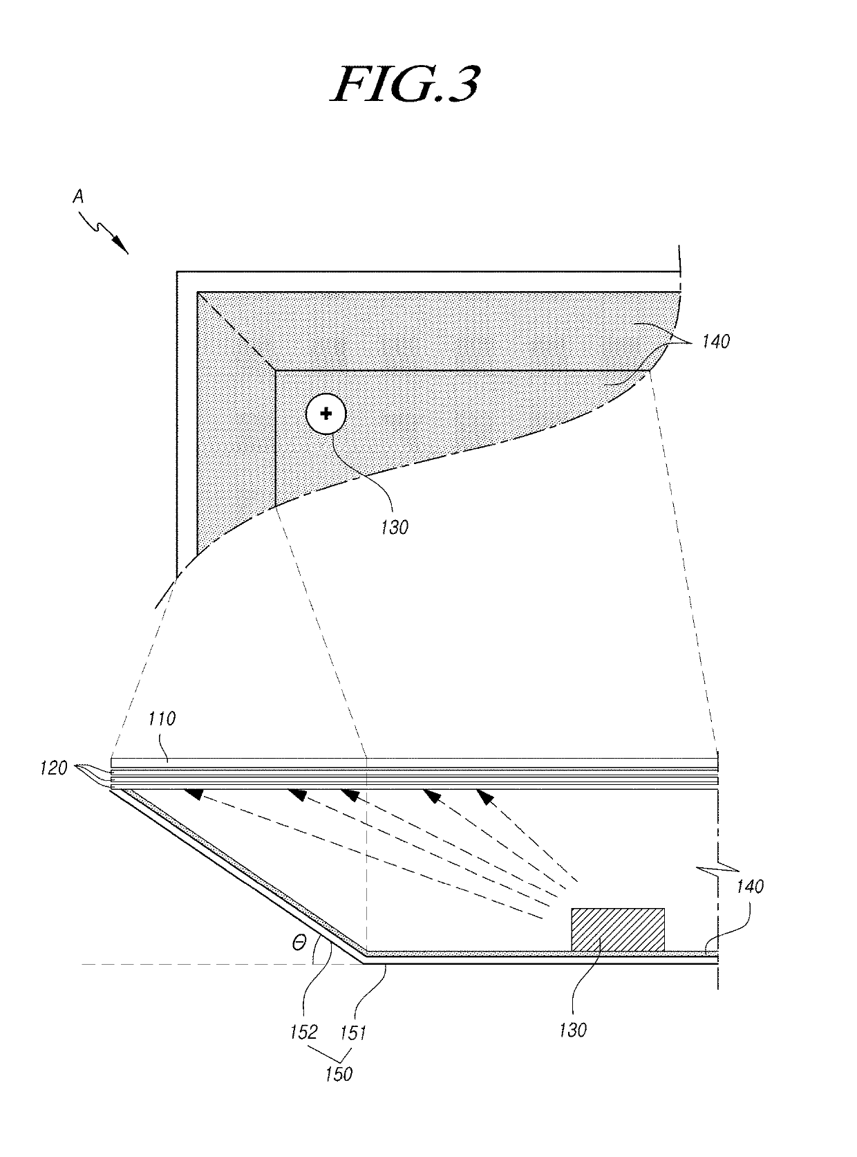
The present invention provides a backlight unit and display device that prevents dark areas and bright lines. This is achieved by using a slimmed backlight unit with a reflective unit disposed on its peripheral area and having a bent structure. A light absorption pattern can also be applied to a portion of the reflective unit to prevent bright lines. These technical effects result in a more uniform brightness of the display device.

Problems solved by technology

As the thickness of the backlight unit reduces, an optical gap between a diffusion plate and a reflective plate reduces, and as a result, there arises a problem that light cannot be supplied sufficiently to a specific area of the display panel.
In this case, light is not sufficiently supplied to a specific area or concentrates in a specific area, and as a result there arises a problem that the uniformity of display brightness is lowered.

Method used


Image

  • Backlight Unit and Display Device
  • Backlight Unit and Display Device
  • Backlight Unit and Display Device

Examples


Embodiment Construction

[0025]Hereinafter, the present embodiments of the disclosure will be described in detail with reference to the accompanying drawings. In denoting elements of the drawings by reference numerals, the same elements will be referenced by the same reference numerals although the elements are illustrated in different drawings. In the following description of the disclosure, detailed description of known functions and configurations incorporated herein may be omitted when it may make the subject matter of the disclosure rather unclear.

[0026]Terms, such as first, second, A, B, (a), or (b) may be used herein to describe elements of the disclosure. Each of the terms is not used to define essence, order, sequence, or number of an element, but is used merely to distinguish the corresponding element from another element. When it is mentioned that an element is “connected” or “coupled” to another element, it should be interpreted that another element may be “interposed” between the elements or th...


PUM


Abstract

Some embodiments of the present disclosure relate to a backlight unit and a liquid crystal display device, in a case where an edge area of a cover bottom is formed in an inclined structure, a reflective unit, such as a reflective sheet, forming a step structure is disposed in the boundary between a bottom surface and an inclined surface of the cover bottom, and thus a sufficient amount of light can be uniformly supplied to a lower portion of the panel corresponding to an edge area of the cover bottom. In addition, since a light absorption pattern is applied to a step structure of the reflective unit, improved luminance and uniformity of light can be provided in an area of the panel corresponding to an inner side of the inclined surface and the inclined surface of the cover bottom.

Description

CROSS-REFERENCE TO RELATED APPLICATION[0001]This application claims the priority benefit of Republic of Korea Patent Application No. 10-2017-0163045, filed on Nov. 30, 2017 in the Republic of Korea Intellectual Property Office, the disclosure of which is incorporated by reference in its entirety.BACKGROUNDTechnical Field[0002]The present disclosure relates to a backlight unit and a display device.Discussion of the Related Art[0003]As the information-oriented society has developed, there has been a growing need for display devices for displaying an image. Recently, various types of display devices, such as a liquid crystal display (LCD) device, a plasma display panel (PDP) device, and an organic light emitting display (OLED) device, have been developed and utilized.[0004]Among these display devices, the liquid crystal display device, by applying a varying electric voltage to liquid crystals arranged in a display panel, allows the alignment of liquid crystals to vary, and thereby prod...

Claims


Application Information

Patent Timeline
IPC IPC(8): G02F1/1335
CPCG02F1/133611G02F1/133605G02F1/133603G02F1/133606G02F2001/133607G02F1/133608G02F1/133308G02F1/133314G02F1/133607
Inventor JUNG, SUNGHYUNLEE, WOOSANG
Owner LG DISPLAY CO LTD
Learn More