
Optical device and display device

a display device and optical technology, applied in the direction of identification means, instruments, polarising elements, etc., can solve the problems of complicated configuration of the display device, and achieve the effect of simple operation and simple configuration

Active Publication Date: 2019-05-23
FUJIFILM CORP
View PDF3 Cites 52 Cited by
  • Summary
  • Abstract
  • Description
  • Claims
  • Application Information

AI Technical Summary

Benefits of technology

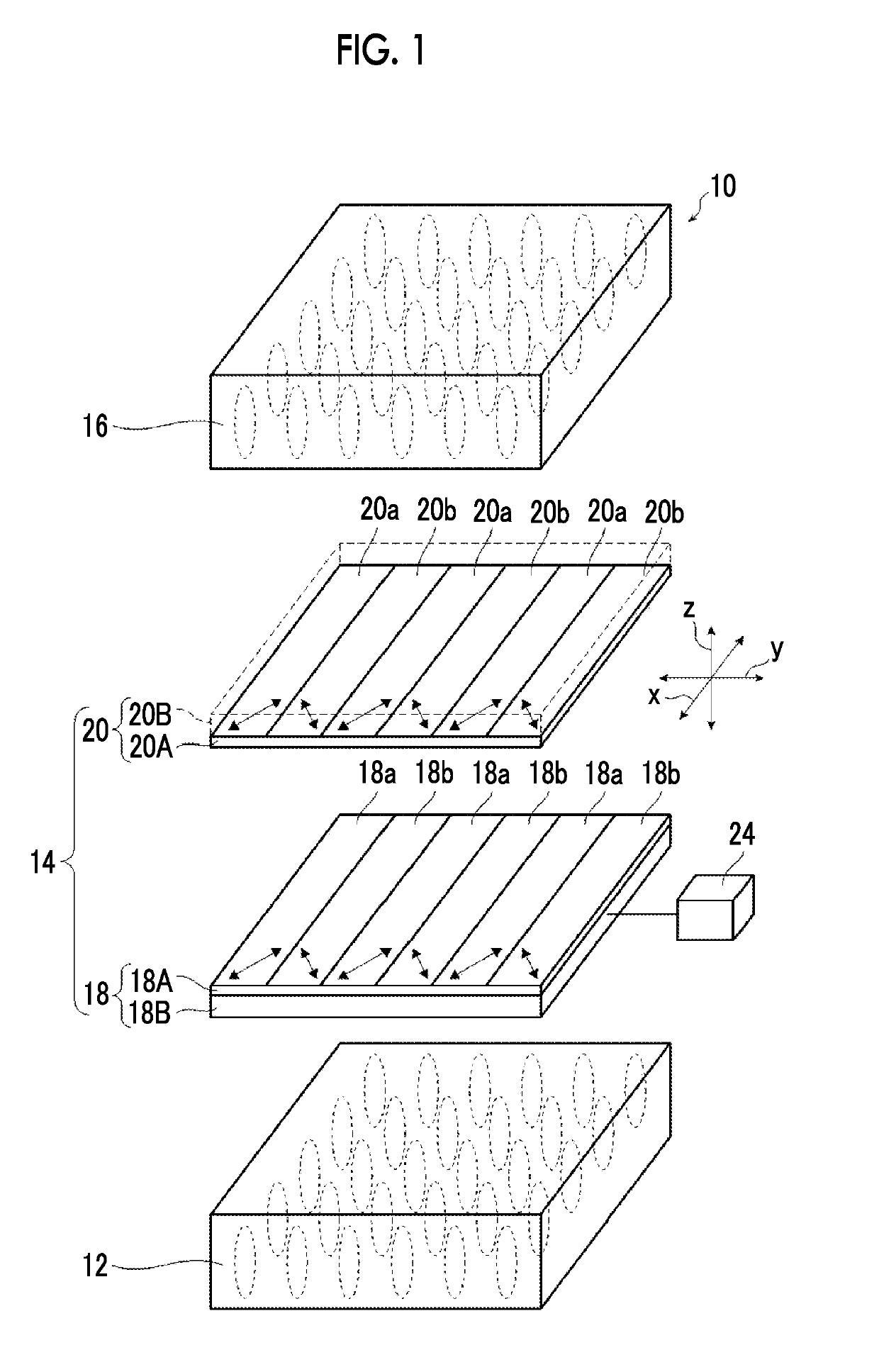
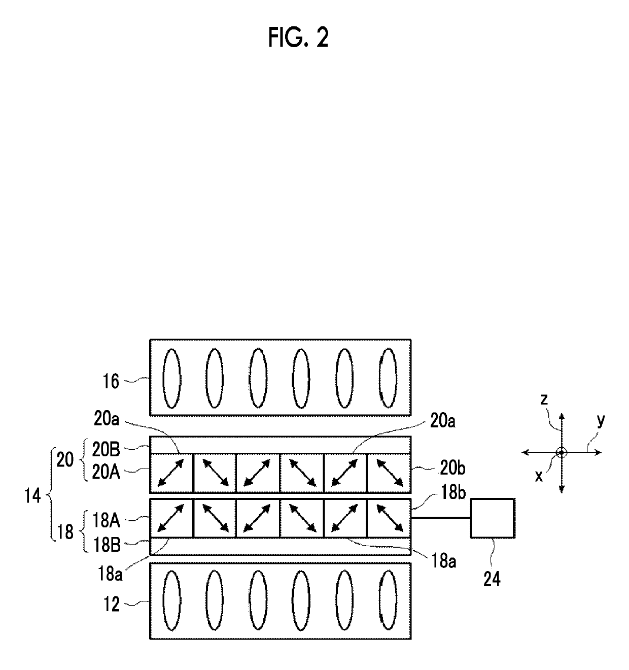
The present invention provides an optical device and a display device that can switch between image display at a wide viewing angle and image display at a narrow viewing angle obtained by limiting the viewing angle. This is achieved by mounting the optical device on a tablet PC or a notebook PC with a simple configuration, without the need for detachment and attachment of a member. The technical effects of the invention are that it provides a more versatile and convenient optical device for display switching between wide and narrow viewing angles in a simple and efficient way.

Problems solved by technology

However, in the liquid crystal display device of JP2007-178979A, the configuration of the display device becomes complicated because the liquid crystal display element needs to have a special structure with W subpixels, a plurality of substrates, and a plurality of common electrodes and the liquid crystal display device needs to be driven in a plurality of different modes.

Method used


Image

  • Optical device and display device
  • Optical device and display device
  • Optical device and display device

Examples


examples

[0212]The features of the present invention will be described in detail with reference to the following examples. The materials, the reagents, the used amounts, the amounts of substances, the ratios, the treatment contents, and the treatment procedures described in the following examples can be appropriately changed within the range not departing from the gist of the present invention. Therefore, the range of the present invention should not be limitatively interpreted by the following specific examples.

example

[0213]

[0214]Each of the following components was put into a mixing tank and stirred while being heated so as to be dissolved, thereby preparing a cellulose acetate solution.

[0215](Composition of Cellulose Acetate Solution)

[0216]Cellulose acetate having acetylation degree of 60.7% to 61.1%: 100 parts by mass

[0217]Triphenyl phosphate (plasticizer): 7.8 parts by mass

[0218]Biphenyl diphenyl phosphate (plasticizer): 3.9 parts by mass

[0219]Methylene chloride (first solvent): 336 parts by mass

[0220]Methanol (second solvent): 29 parts by mass

[0221]1-Butanol (third solvent): 11 parts by mass

[0222]16 parts by mass of the following retardation enhancer (A), 92 parts by mass of methylene chloride, and 8 parts by mass of methanol were put into another mixing tank and stirred while being heated, thereby preparing a retardation enhancer solution.

[0223]25 parts by mass of the retardation enhancer solution was mixed with 474 parts by mass of the cellulose acetate solution, and the resulting solution...


PUM

PropertyMeasurementUnit
viewing angleaaaaaaaaaa
angleaaaaaaaaaa
wavelengthaaaaaaaaaa

Abstract

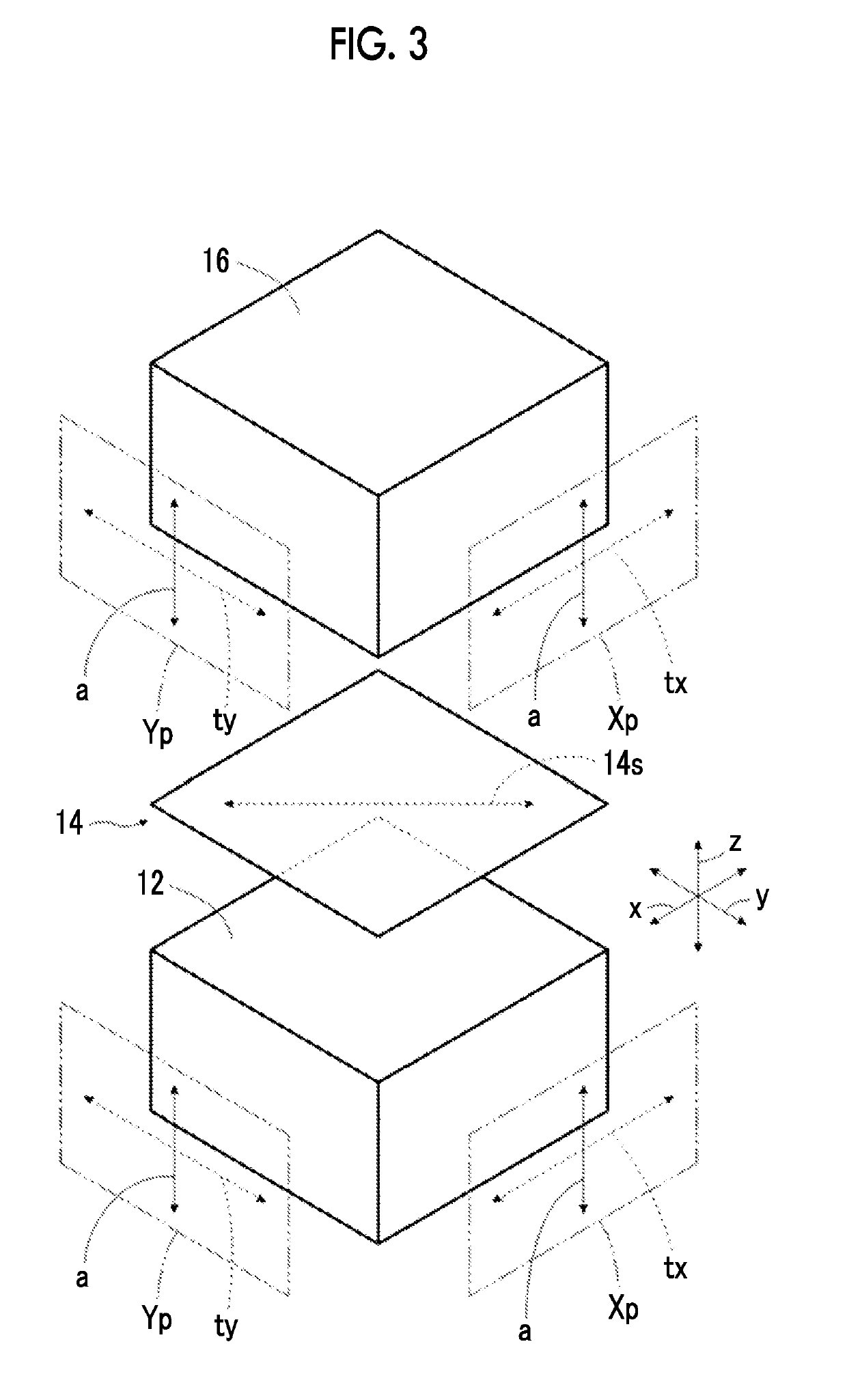
An optical device includes a first polarizer which has an absorption axis in a thickness direction; a second polarizer which has an absorption axis in a thickness direction; and a functional layer which is disposed between the first polarizer and the second polarizer and is capable of switching between a state in which an in-plane retardation is 0 and a state in which an in-plane retardation is greater than 0. A display device includes a display element; and the optical device.

Description

CROSS-REFERENCE TO RELATED APPLICATIONS[0001]This application is a Continuation of PCT International Application No. PCT / JP2017 / 020170 filed on May 31, 2017, which claims priority under 35 U.S.C. §119(a) to Japanese Patent Application No. 2016-130141 filed on Jun. 30, 2016. Each of the above application(s) is hereby expressly incorporated by reference, in its entirety, into the present application.BACKGROUND OF THE INVENTION1. Field of the Invention[0002]The present invention relates to an optical device used for a display device such as a liquid crystal display device and a display device using this optical device.2. Description of the Related Art[0003]In personal electronic devices, for example, tablet personal computers (PCs), notebook PCs, and mobile phones such as smartphones, there is a demand that users do not want their screens to be peeped by the surrounding third parties. Therefore, in these electronic devices, it has been attempted to narrow the viewing angle of a screen ...

Claims


Application Information

Patent Timeline
Patent Type & Authority Applications(United States)
IPC IPC(8): G02B5/30G02B5/18G02F1/1335
CPCG02B5/3025G02B5/1833G02F1/133528G02B2207/123G02B5/3016G02B5/3083G02F1/1323G02F1/133531G02F1/133631G02F1/133633G09F9/00G02F1/1335
Inventor YANAI, YUJIRO
Owner FUJIFILM CORP
Learn More