
Systems and methods for vibration detection

a computed tomography and vibration detection technology, applied can solve problems such as image artifacts or other image quality issues of the ct system, and achieve the effect of detecting vibration in the field of medical imaging

Active Publication Date: 2019-05-23
GENERAL ELECTRIC CO
View PDF1 Cites 6 Cited by
  • Summary
  • Abstract
  • Description
  • Claims
  • Application Information

AI Technical Summary

Benefits of technology

The patent is about a method for detecting vibrations in a computed tomography (CT) system. This is done by using a balance sensor that is attached to the stationary housing of the system and measuring the vibration level of the rotating gantry. The sensor can output a notification if the vibration level exceeds a certain threshold, which indicates potential image quality issues caused by the vibrations. This helps to improve image quality and prevent image artifacts caused by vibrations during CT scans.

Problems solved by technology

In this way, vibrations of the CT system that may produce image artifacts or other image quality issues may be detected with an on-board balance sensor.

Method used


Image

  • Systems and methods for vibration detection
  • Systems and methods for vibration detection
  • Systems and methods for vibration detection

Examples


Embodiment Construction

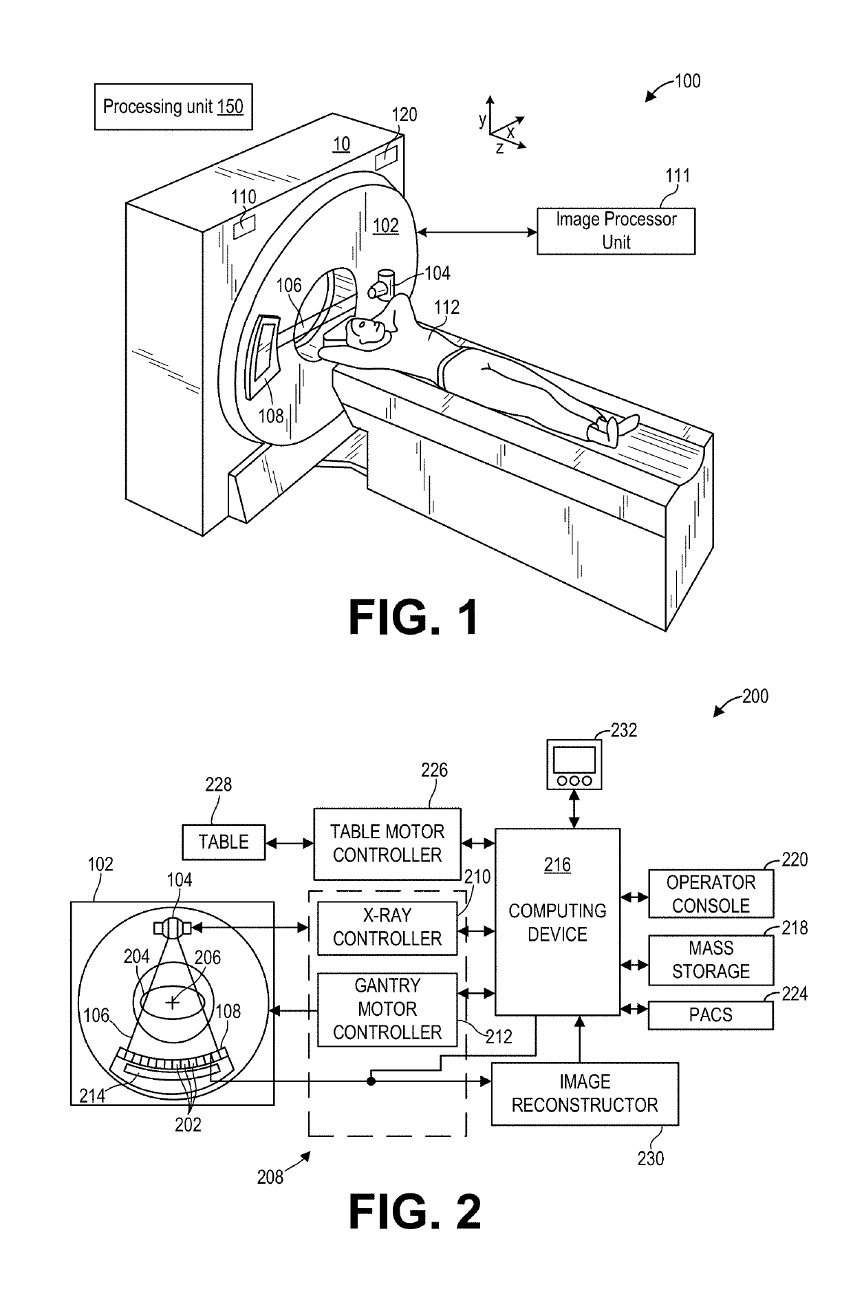
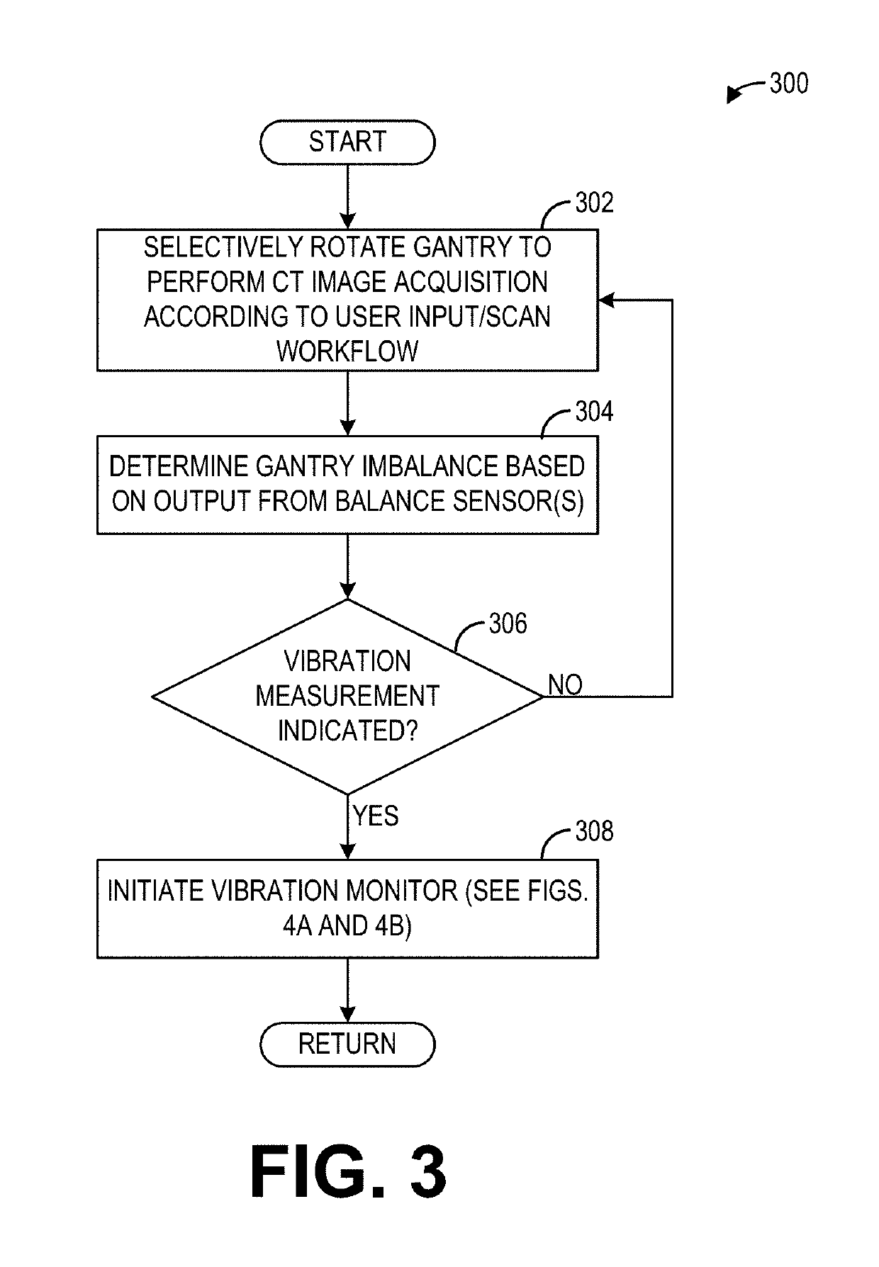
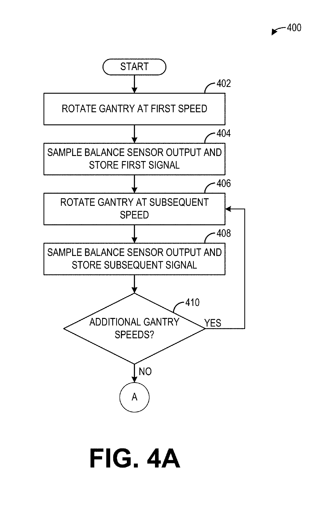
[0012]The following description relates to various embodiments of measuring vibration of a computed tomography (CT) scanner. Traditionally, CT scanners may have sensors on board the CT scanner that are used to measure gantry imbalance (imbalance occurs once per rotation), but are not used to measure full gantry vibration which can have different harmonics occurring at more than once per rotation. Typically, to measure vibration, expensive external laboratory-type commercial analyzers may be used when the CT scanner is being built or refurbished at the factory. Then, because external laboratory-type commercial vibration analyzers are not usually suitable for field service usage due to their high cost and required training, gantry imbalance measurements may relied upon for detecting gantry rotation issues once the CT scanner is installed in a location. However, many factors may effect gantry vibration after installation in addition to imbalance, including floor stiffness and gantry an...


PUM


Abstract

Methods and systems are provided for measuring vibrations in an imaging system. In one embodiment, a method for a computed tomography (CT) system includes measuring a vibration level of a rotatable gantry of the CT system with a balance sensor coupled to a stationary housing of the CT system and outputting a notification indicating potential image artifacts based on the vibration level exceeding a vibration threshold.

Description

FIELD[0001]Embodiments of the subject matter disclosed herein relate to medical imaging, and more particularly, to detecting vibration in a computed tomography scanner.BACKGROUND[0002]Non-invasive imaging technologies allow images of the internal structures of a patient or object to be obtained without performing an invasive procedure on the patient or object. In particular, technologies such as computed tomography (CT) use various physical principles, such as the differential transmission of x-rays through the target volume, to acquire image data and to construct tomographic images (e.g., three-dimensional representations of the interior of the human body or of other imaged structures). CT scanners may include a rotatable gantry on which a radiation source and detectors are mounted. The vibration of the gantry as it rotates directly translates to degradation in image quality, as gantry vibration can distort images and create streaks / artifacts in the patient data.BRIEF DESCRIPTION[0...

Claims


Application Information

Patent Timeline
Patent Type & Authority Applications(United States)
IPC IPC(8): A61B6/00A61B6/03
CPCA61B6/586A61B6/032A61B6/4435A61B6/035A61B6/5205A61B6/527
Inventor SMITH, CHAD ALLANREZNICEK, MARK EDMUNDFRIEDLANDER, ARIEL
Owner GENERAL ELECTRIC CO
Learn More