
Fuel cell system

a fuel cell and system technology, applied in the direction of fuel cells, motive system fuel cells, electrical devices, etc., can solve the problems of not being able to achieve the purpose of oxygen consumption process, the amount of oxygen not consumed and remaining in the cathode may increase,

Active Publication Date: 2019-05-16
TOYOTA JIDOSHA KK
View PDF0 Cites 2 Cited by
  • Summary
  • Abstract
  • Description
  • Claims
  • Application Information

AI Technical Summary

Benefits of technology

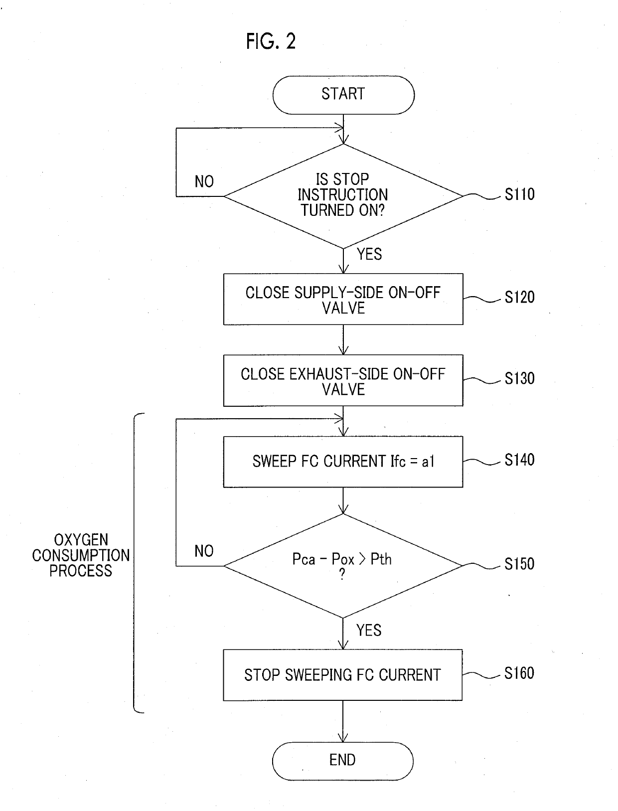
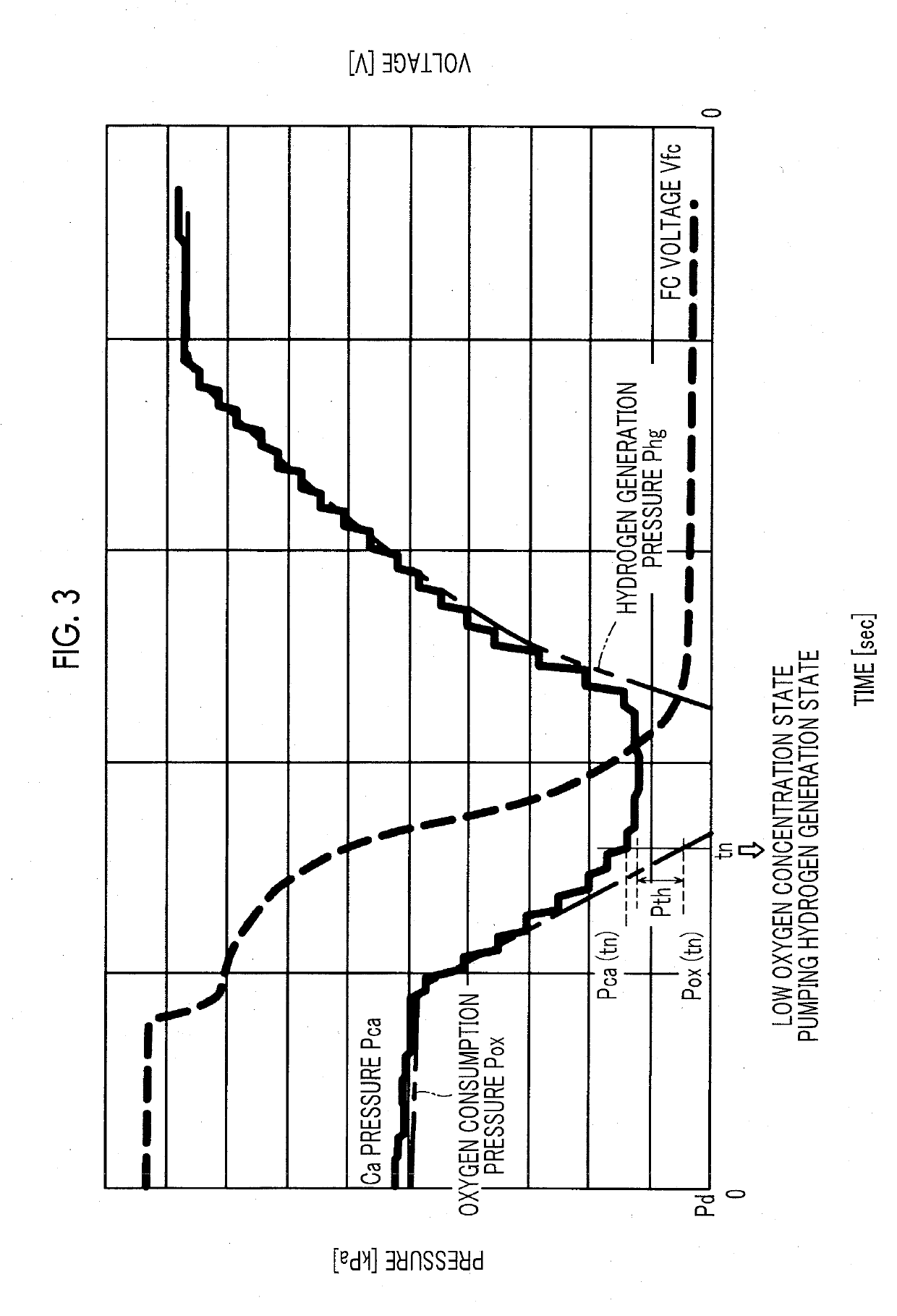
The fuel cell system described in this patent has a controller that can detect when the fuel cell is producing low levels of pumping hydrogen. This is done by monitoring the pressure of the cathode, which decreases when the fuel cell is running. By setting a threshold for the voltage output, the controller can easily stop sweeping the current when the pressure difference reaches a certain level, without needing to detect the pressure of the cathode. This allows for easier control and management of the fuel cell system.

Problems solved by technology

On the other hand, when the processing time is too short, the amount of oxygen not consumed and remaining in the cathode may increase, and thus the purposes of the oxygen consumption process may not be achieved.

Method used


Image

  • Fuel cell system
  • Fuel cell system
  • Fuel cell system

Examples


first embodiment

A. First Embodiment

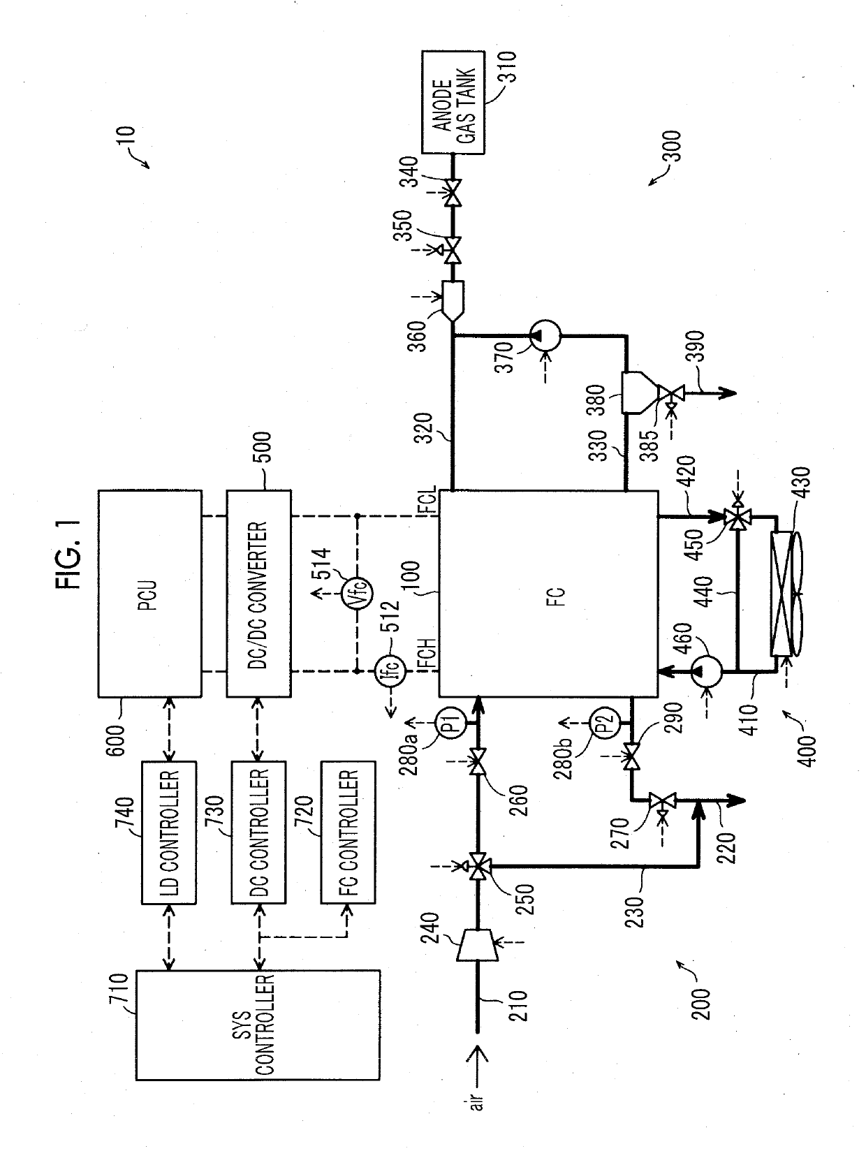
[0016]FIG. 1 is an explanatory diagram showing a schematic configuration of a fuel cell system 10 according to a first embodiment of the present disclosure. The fuel cell system 10 is mounted on, for example, a vehicle (fuel cell vehicle) and outputs electric power to be a power source of the vehicle in response to a request from a driver. The fuel cell system 10 includes a fuel cell (FC) 100, a cathode gas supply unit 200, an anode gas supply unit 300, a FC cooling unit 400, a DC / DC converter 500, a power control unit 600, a SYS controller 710, a FC controller 720, a DC controller 730, a LD controller 740, a FC current sensor 512, and a FC voltage sensor 514. The power control unit 600 is hereinafter also referred to as “PCU 600”.

[0017]The fuel cell 100 has a stack structure in which a plurality of unit cells (not shown) is stacked as power generation elements. The unit cell is constituted by a membrane electrode assembly and two separators sandwiching an anode a...

second embodiment

B. Second Embodiment

[0046]FIG. 4 is an explanatory diagram showing a schematic configuration of a fuel cell system 10B in the second embodiment. In the fuel cell system 10B, the cathode gas supply unit 200 (FIG. 1) of the fuel cell system 10 is replaced with a cathode gas supply unit 200B not having the supply-side pressure sensor 280a and the exhaust-side pressure sensor 280b, and the oxygen consumption process by the FC controller 720 is executed differently as will be described later. The other configuration of the fuel cell system 10B is the same as that of the fuel cell system 10 of the first embodiment.

[0047]FIG. 5 is a flowchart showing a procedure of the oxygen consumption process executed at the time of stopping the fuel cell system 10B. The processing is executed by the FC controller 720.

[0048]Similarly to the oxygen consumption process (FIG. 2) of the first embodiment, in a case where the stop instruction is turned ON (step S110: YES), the FC controller 720 closes the sup...


PUM


Abstract

In a fuel cell system, a controller is configured to, to stop the fuel cell system, (a) execute an oxidizing gas consumption process by supplying a fuel gas to an anode and sweeping current from a fuel cell while a supply-side on-off valve and an exhaust-side on-off valve are closed to seal the remaining oxidizing gas in the cathode, and (b) stop sweeping the current at a time point at which the difference between pressure of the cathode that decreases in response to the sweeping of the current and an estimated pressure value of the cathode that decreases by consumption of the oxidizing gas remaining in the cathode in response to the sweeping of the current becomes larger than a predetermined determination threshold value to end the oxidizing gas consumption process.

Description

INCORPORATION BY REFERENCE[0001]The disclosure of Japanese Patent Application No. 2017-217880 filed on Nov. 13, 2017 including the specification, drawings and abstract is incorporated herein by reference in its entirety.BACKGROUND1. Technical Field[0002]The present disclosure relates to a fuel cell system.2. Description of Related Art[0003]At the time of stopping a fuel cell system, a process of consuming oxygen remaining in the cathode of the fuel cell (oxygen consumption process) is executed. The oxygen consumption process is a process in which the current is swept in a manner that decreases the output voltage of the fuel cell to control the output voltage until the output voltage lowers to a predetermined voltage value, as described in, for example, Japanese Unexamined Patent Application Publication No. 2016-012461 (JP 2016-012461 A).SUMMARY[0004]In the oxygen consumption process, the amount of oxygen that could be consumed increases as the predetermined voltage value decreases, ...

Claims


Application Information

Patent Timeline
IPC IPC(8): H01M8/04303H01M8/0438H01M8/04537H01M8/04746H01M8/04858
CPCH01M8/04303H01M8/0441H01M8/04552H01M8/04753H01M8/04761H01M8/04902H01M2250/20H01M8/0494H01M8/0491Y02E60/50
Inventor YAMAMORI, KEITAROKAKIMI, YOSUKE
Owner TOYOTA JIDOSHA KK
Learn More