
Double acting positive displacement fluid pump

a positive displacement, fluid pump technology, applied in the direction of pumps, mechanical equipment, liquid fuel engines, etc., can solve the problems of limited power, achieve the effect of reducing the downtime for repair and maintenance, reducing the downtime for maintenance, and being easy to insert and retra

Active Publication Date: 2019-05-16
OLDENAMP
View PDF8 Cites 19 Cited by
  • Summary
  • Abstract
  • Description
  • Claims
  • Application Information

AI Technical Summary

Benefits of technology

The invention provides a double acting fluid pump that can handle normal fluids, gases, and fluids with low to high contents of solids and has the following features: less susceptible to fatigue failure, longer pump stroke, improved packing and valve life, and provides double the output of a conventional pump with less pressure pulsations. The pump has a check valve at the fluid exit end or at the entry point of a common manifold to prevent loss of prime or failure of the pump. The invention also includes a hollow plunger with conical bore acting as a diffuser to reduce turbulence and wear and erosion of the pump chamber. The invention further includes a hydraulic packing adjustment device that provides a constant but remotely adjustable force on the packing rings leading to a prolonged life span of the pump and a controller for controlling and monitoring the operation of the plunger drive and the hydraulic cylinder. The double acting positive displacement fluid pump is easy to maintain and the output can be easily manipulated during operation.

Problems solved by technology

With the combined suction / discharge valve in open position during the compression stroke of the inlet portion the one half of the fluid providing pressurized fill for the outlet chamber is (substantial) pressure balanced across the relative displacement areas of the inlet and outlet portion and therefor it requires limited power to transfer this portion of the fluid from the inlet chamber to the outlet chamber.

Method used


Image

  • Double acting positive displacement fluid pump
  • Double acting positive displacement fluid pump
  • Double acting positive displacement fluid pump

Examples


first embodiment

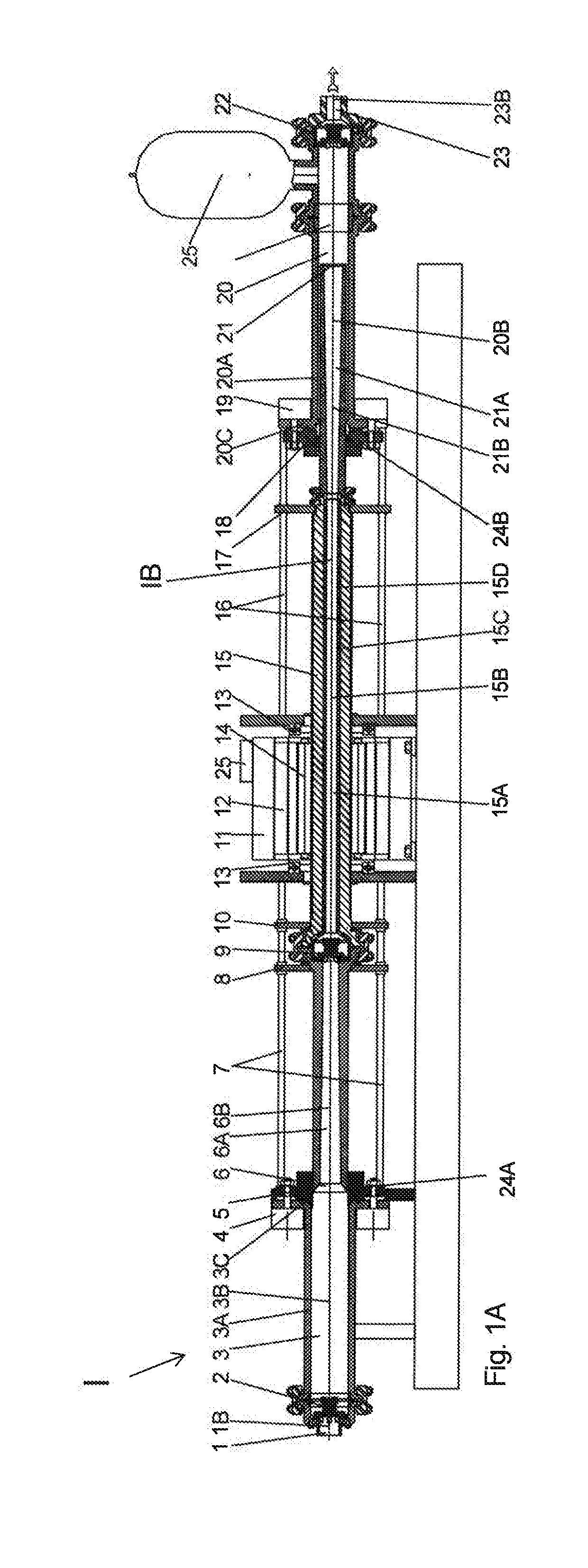
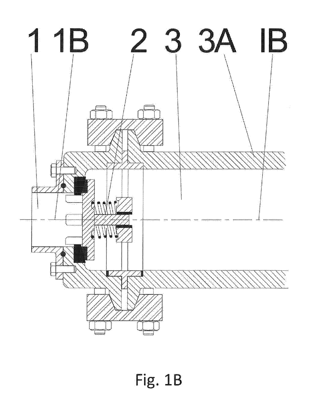
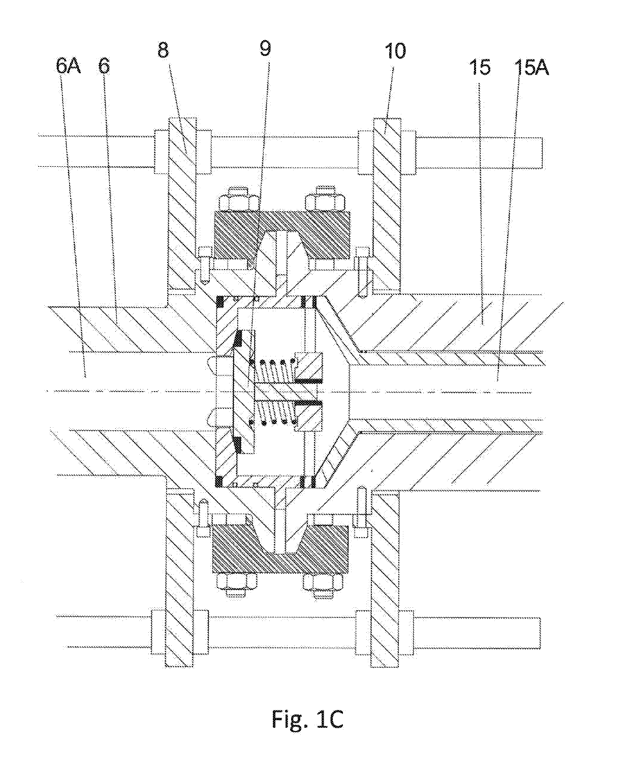
[0022]In FIG. 1A a double acting positive displacement fluid pump in accordance with the invention driven by a hollow shaft electric torque motor is schematically shown in cross section. FIG. 1B shows the inlet suction valve assembly thereof in an enlarged view, FIG. 1C shows the combined suction-discharge valve thereof in an enlarged view; and FIG. 1D shows the outlet discharge valve assembly thereof in an enlarged view. FIG. 1E shows the hydraulic packing arrangement thereof in an enlarged view. FIG. 1F shows a second fluid conduit inside the bore of the screw shaft.

second embodiment

[0023]FIG. 2 in cross section schematically shows a double acting fluid pump in accordance with the invention driven by a crankshaft mechanism; and

[0024]FIG. 3 in cross section schematically shows an embodiment of a double acting fluid pump in accordance with the invention configured as a downhole pump.

[0025]The double acting positive displacement fluid pump I shown in FIG. 1A has a first housing 3A comprising a cylindrical pump fluid inlet chamber 3, and a second housing 20A, separate from the first housing 3A, comprising a cylindrical pump fluid outlet chamber 20.

[0026]The pump fluid inlet chamber 3 is in fluid communication with the pump fluid outlet chamber 20 by means of a reciprocatingly drivable hollow plunger 6, 15, 21 having a through passage 6A, 15A, 21A. The hollow plunger has an inlet portion 6 positioned within the pump fluid inlet chamber 3 and an outlet portion 21 positioned within the pump fluid outlet chamber 20. The inlet portion 6 and the outlet portion 21 of the ...


PUM


Abstract

Double acting positive displacement fluid pump Double acting positive displacement fluid pump having two or more housings (3A,20A), a first housing (3A) comprising a pump fluid inlet chamber (3) and a separate housing (20A) comprising a pump fluid outlet chamber (20), the pump fluid inlet chamber (3) being in fluid communication with the pump fluid outlet chamber (20) by means of a through passage (6A), said through passage (6A) having an inlet positioned within the pump fluid inlet chamber (3) and an outlet positioned within the pump fluid outlet chamber (20), the inlet portion (6) of the plunger having an effective displacement area which is larger than the effective displacement area of the outlet portion (21) of the plunger, said passage being further provided with a combined suction-discharge valve assembly (9) arranged in the through passage, wherein the pump fluid inlet chamber (3) comprises a central pump fluid inlet chamber axis and a fluid entry (1B) having an inlet suction valve assembly (2), the pump fluid outlet chamber (20) comprises a central pump fluid outlet chamber axis and the through passage comprises a through passage axis, wherein the central pump fluid inlet chamber axis, the central pump fluid outlet chamber axis and the through passage axis are coaxial and form a central double acting positive displacement fluid pump axis.

Description

BACKGROUND OF THE INVENTION[0001]The invention relates to a double acting positive displacement fluid pump.[0002]In general the present invention relates to high pressure reciprocating pumps which are used in for example the oil and gas industry for pumping drilling mud, pumping cement for zonal isolation, pumping fracturing fluids and chemical compositions for production enhancement purposes and pumping cryogenic fluids like liquid nitrogen and liquid CO2. High pressure reciprocating pumps are also in the field of industrial services for inter alia water jetting and cleaning purposes.[0003]These reciprocating pumps can be of a piston type pump or a plunger type pump where a plunger pump is defined as a type of positive displacement pump where the high-pressure seal is stationary and a smooth cylindrical plunger slides through the seal and a piston pump is a type of positive displacement pump where the high-pressure seal reciprocates with the piston. For all intents and purposes in ...

Claims


Application Information

Patent Timeline
IPC IPC(8): F04B5/02F04B47/02F04B49/20
CPCF04B5/02F04B47/02F04B49/20F04B1/12F04B5/00F04B19/22F04B49/065F04B53/10
Inventor DAVIDS, HENDRIK BEREND
Owner OLDENAMP
Learn More