
Annulus filler

a filler and annulus technology, applied in the field of annulus filler, can solve the problems of rear interface wear, repair costs, rear interface wear, etc., and achieve the effects of reducing the risk of defects at joints, and facilitating the removal of mandrels

Active Publication Date: 2019-05-16
ROLLS ROYCE PLC
View PDF0 Cites 2 Cited by
  • Summary
  • Abstract
  • Description
  • Claims
  • Application Information

AI Technical Summary

Benefits of technology

The patent text is about a design for a product's body part that has a separate rear lip. This makes it easier to form the body part using a molding process. The rear lip can be attached to the body part using contact surfaces, which strengthens the connection between them. This design helps to prevent weakness at the joints between parts.

Problems solved by technology

Such composite annulus fillers are lightweight, and, in the event of damage, may be replaced independently of the blades.
Furthermore, the rear lip is subject to wear, and so by forming the rear lip on a separate part, only the rear interface portion can be replaced, rather than the whole annulus filler, thus reducing repair costs.
The abutment part means that friction between the annulus filler and rear element only causes wear on the rear interface portion, and not the whole annulus filler.
Furthermore, the rear lip is subject to wear, and so by forming the rear lip on a separate part, only the rear interface portion can be replaced, rather than the whole annulus filler.

Method used


Image

  • Annulus filler
  • Annulus filler
  • Annulus filler

Examples


Embodiment Construction

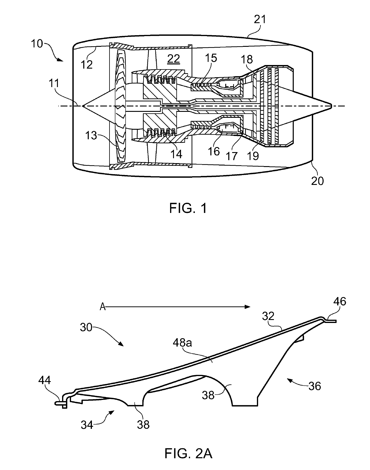
[0045]With reference to FIG. 1, a gas turbine engine is generally indicated at 10, having a principal and rotational axis 11. The engine 10 comprises, in axial flow series, an air intake 12, a propulsive fan 13, an intermediate pressure compressor 14, a high-pressure compressor 15, combustion equipment 16, a high-pressure turbine 17, an intermediate pressure turbine 18, a low-pressure turbine 19 and an exhaust nozzle 20. A nacelle 21 generally surrounds the engine 10 and defines both the intake 12 and the exhaust nozzle 20.

[0046]The gas turbine engine 10 works in the conventional manner so that air entering the intake 12 is accelerated by the fan 13 to produce two air flows: a first air flow into the intermediate pressure compressor 14 and a second air flow which passes through a bypass duct 22 to provide propulsive thrust. The intermediate pressure compressor 14 compresses the air flow directed into it before delivering that air to the high pressure compressor 15 where further comp...


PUM

PropertyMeasurementUnit
volumeaaaaaaaaaa
friction wearaaaaaaaaaa
timeaaaaaaaaaa

Abstract

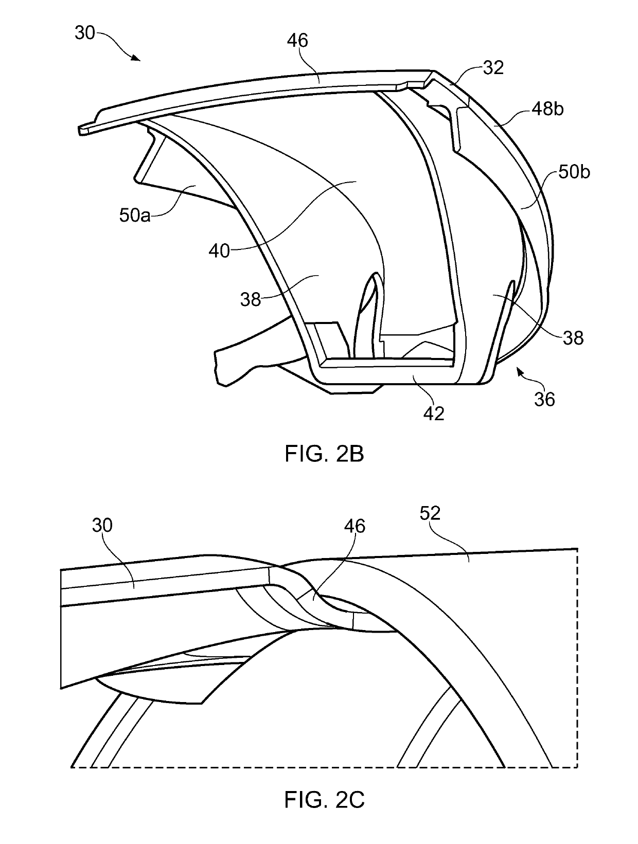
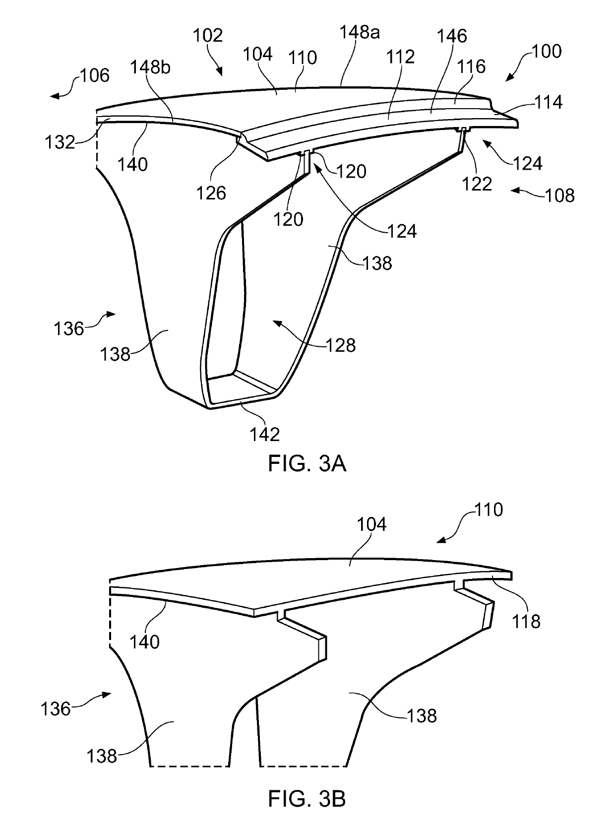
An annulus filler for mounting to a rotor disc in a gas turbine engine includes a body portion having a top wall arranged to bridge the gap between two adjacent blades extending from the rotor disc and to define an air flow surface for air passing between the blades; and a separately formed rear interface portion, fixed to the body portion adjacent to a down-flow end of the top wall. The rear interface portion forms a lip projecting below the top wall.

Description

CROSS-REFERENCE TO RELATED APPLICATIONS[0001]This application is based upon and claims the benefit of priority from British Patent Application Number 1718600.8 filed 10 Nov. 2017, the entire contents of which are incorporated by reference.BACKGROUND1. Field of the Disclosure[0002]The present disclosure concerns an annulus filler for mounting to a rotor disc in a gas turbine engine, and a method of manufacturing an annulus filler.2. Description of the Related Art[0003]Gas turbine engines include a number of rotating fan systems (also referred to as fans). The fans comprise a plurality of radially extending blades mounted on a rotor disc, and may be provided in the compressor stage or turbine stage of the engine, or as the propulsion fan.[0004]To ensure a radially smooth inner surface for air as it passes over the rotor disc, annulus fillers can be used to bridge the gap between adjacent blades. It is known to provide annulus fillers with engagement features for removably attaching th...

Claims


Application Information

Patent Timeline
Patent Type & Authority Applications(United States)
IPC IPC(8): F01D5/22F01D11/00F01D5/30F02K3/06
CPCF01D5/225F01D11/008F05D2220/36F02K3/06F01D5/3007F05D2300/44F05D2240/57F05D2300/603Y02T50/60B29C70/68
Inventor THOMPSON, EWAN F.CARTY, ELLIOT
Owner ROLLS ROYCE PLC
Learn More