Centrifugal separator with a sensor device

Active Publication Date: 2019-05-16
ALFA LAVAL CORP AB
View PDF0 Cites 5 Cited by
  • Summary
  • Abstract
  • Description
  • Claims
  • Application Information

AI Technical Summary

Benefits of technology

The present invention provides a sensor device that can reliably measure various parameters and conditions of a centrifugal separator. It has low sensitivity to disturbances and defects. The transfer element is directed so that the end face of the receiving head faces the opening of a nozzle at a right angle, allowing the jets from the nozzles to transmit vibrations and shock pulses directly into the transfer element and provide a strong signal for the sensor element to register. The sensor element comprises a shock pulse transducer with an accelerometer, which can securely sense vibrations with the desired frequencies. The transfer element is protected from splashing and vibrations not generated from the receiving head by a surrounding protecting tube.

Problems solved by technology

Furthermore, it is aimed at a sensor device having a low sensitivity to disturbances and defects.

Method used


Image

  • Centrifugal separator with a sensor device
  • Centrifugal separator with a sensor device
  • Centrifugal separator with a sensor device

Examples


Embodiment Construction

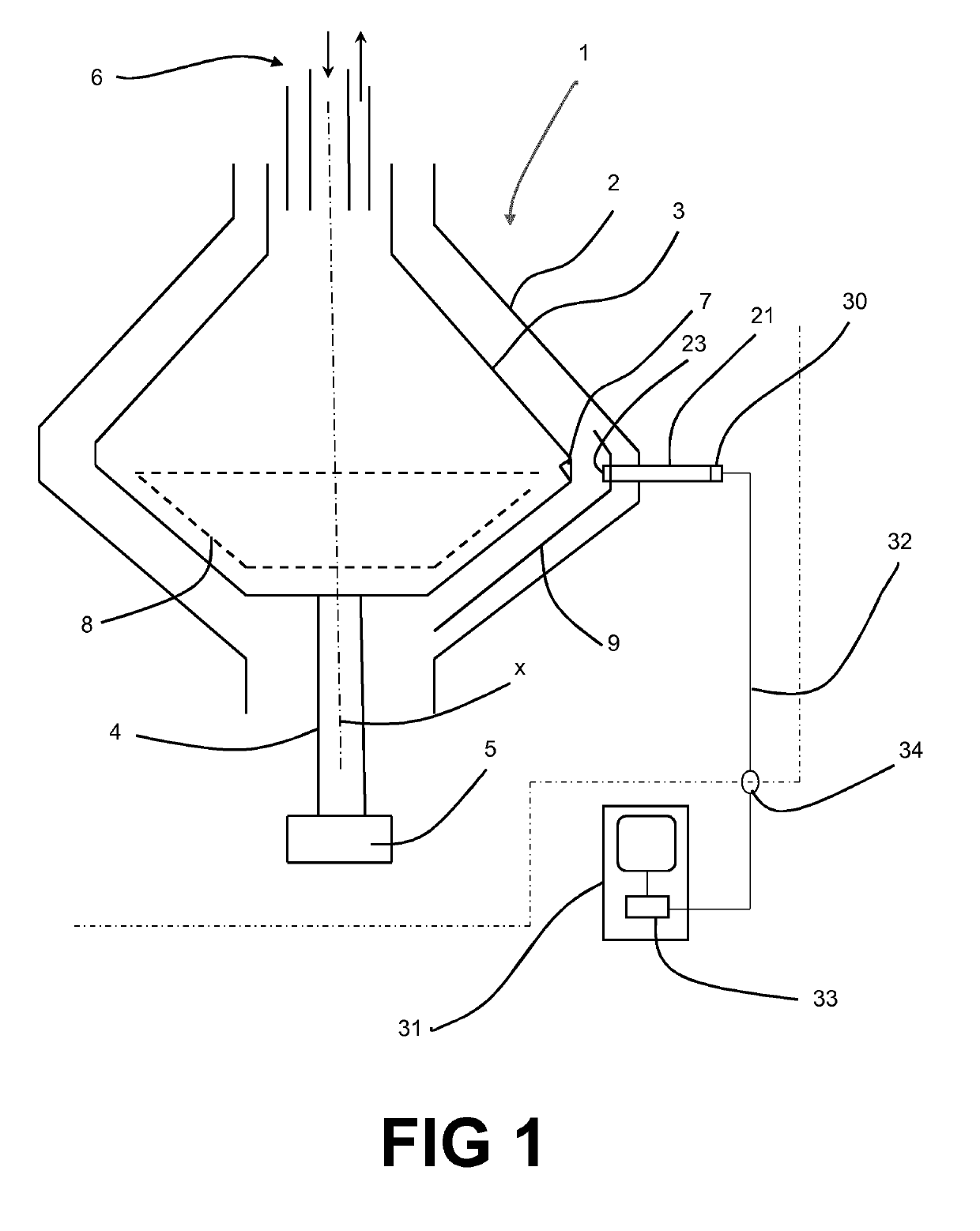
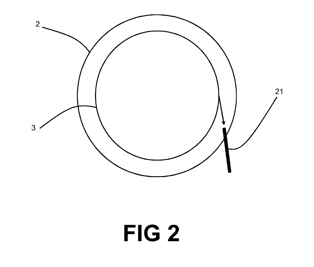
[0022]FIG. 1 discloses a centrifugal separator 1 having a stationary casing 2 and a centrifuge rotor 3 which is provided to rotate around an axis x of rotation in the stationary casing 2. The centrifuge rotor 3 is driven via a spindle 4 by a schematically indicated drive motor 5. The centrifugal separator 1 comprises inlet and outlet conduits which are schematically indicated at 6 and which are configured in a manner known per se.

[0023]Furthermore, the centrifuge rotor 3 comprises a plurality of nozzles 7 for discharge of a product, such as liquid, which for instance may comprise or consist of sludge. The nozzles 7 may be permanently open nozzles. The nozzles 7 may alternatively be intermittently openable nozzles which may open in a manner known per se by means of a schematically indicated valve disc 8 provided within the centrifuge rotor 3. The nozzles 7 are distributed, or preferably uniformly distributed, along the periphery of the centrifuge rotor 3. Outside the nozzles 7, a gui...


PUM


Abstract

A centrifugal separator has a stationary casing and a centrifuge rotor, which is provided in the stationary casing and arranged to rotate around an axis of rotation at a rotary speed and which includes a plurality of nozzles for discharge of a product from the centrifuge rotor. The centrifugal separator includes a sensor device which includes a transfer element, which has a first part and a second part and which is configured to be mounted in such a way that the first part is located inside the stationary casing and outside the centrifuge rotor and that the second part is located outside the stationary casing. At least the first part of the transfer element has an elongated shape, a receiving head, which includes the first part of the transfer element. The sensor device further includes a sensor element, which is mounted to the second part of transfer element and which is configured to sense vibrations and / or shock pulses propagating from the receiving head to the sensor element, and an evaluation unit, which communicates with the sensor element for transmitting signals from the sensor element to the evaluation unit. The transfer element is mounted in the stationary casing, directed such that the end face of the receiving head faces the passing jets from the nozzles during rotation of the rotor. A centrifugal separator with such a sensor device is also disclosed.

Description

THE BACKGROUND OF THE INVENTION AND PRIOR ART[0001]The present invention refers generally to the supervision of the operation of centrifugal separators having nozzles for the discharge of a product, such as a liquid, which for instance comprises or consists of sludge. More precisely, the invention refers to a centrifugal separator having a stationary casing and a centrifuge rotor, which is provided in the stationary casing and arranged to rotate around an axis of rotation at a rotary speed and which comprises a plurality of nozzles for discharge of a product from the centrifuge rotor in a direction, wherein the centrifugal separator comprises a sensor device, which comprises a transfer element, which has a first part and a second part and which is configured to be mounted in such a way that the first part is located inside the stationary casing and outside the centrifuge rotor and that the second part is located outside the stationary casing, wherein at least the first part of the t...

Claims


Application Information

Patent Timeline
IPC IPC(8): B04B7/06B04B1/10B04B11/04B04B13/00G01M3/24G01P15/09G01P3/26
CPCB04B7/06B04B1/10B04B11/04B04B13/00G01M3/24G01P15/09G01P3/26
Inventor SUNDIN, MAGNUS
Owner ALFA LAVAL CORP AB
Why Eureka
Try Eureka