
Vehicle control device

a technology of vehicle control and control device, which is applied in the direction of process and machine control, transportation and packaging, instruments, etc., can solve the problems of unknowing a time, inconvenience for the occupant of the vehicle, and so as to achieve the effect of suppressing the uneasiness of the crossing person

Active Publication Date: 2019-05-09
TOYOTA JIDOSHA KK
View PDF6 Cites 10 Cited by
  • Summary
  • Abstract
  • Description
  • Claims
  • Application Information

AI Technical Summary

Benefits of technology

This patent aims to make it easier for people to recognize the vehicle's traffic information and know when the vehicle will start moving. This will help people feel more comfortable and informed about the crosswalk experience.

Problems solved by technology

When the vehicle travels, that is, when the crossing of the road by the person is dangerous, the person crossing assistance notification system causes red light to light up to transmit the fact that the crossing of the road is dangerous to the person.
However, the person in the vehicle advancing direction does not know a time before the vehicle starts to travel.
Thus, there is a possibility that a crossing person feels uneasiness that the vehicle may depart before the crossing is completed.
When the time before the vehicle starts to travel becomes long, there is also a possibility that an occupant of the vehicle feels annoying.

Method used


Image

  • Vehicle control device
  • Vehicle control device
  • Vehicle control device

Examples


first embodiment

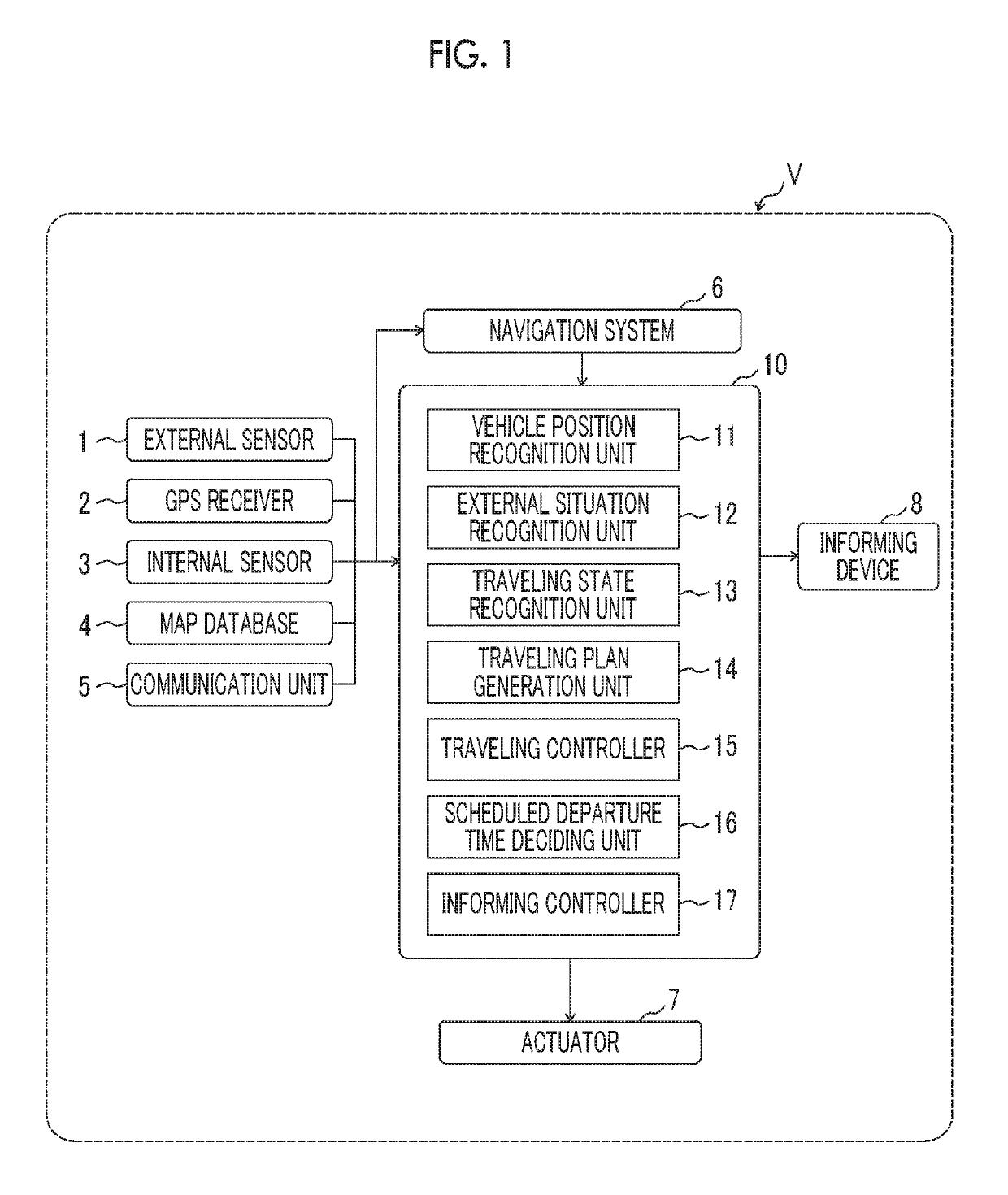
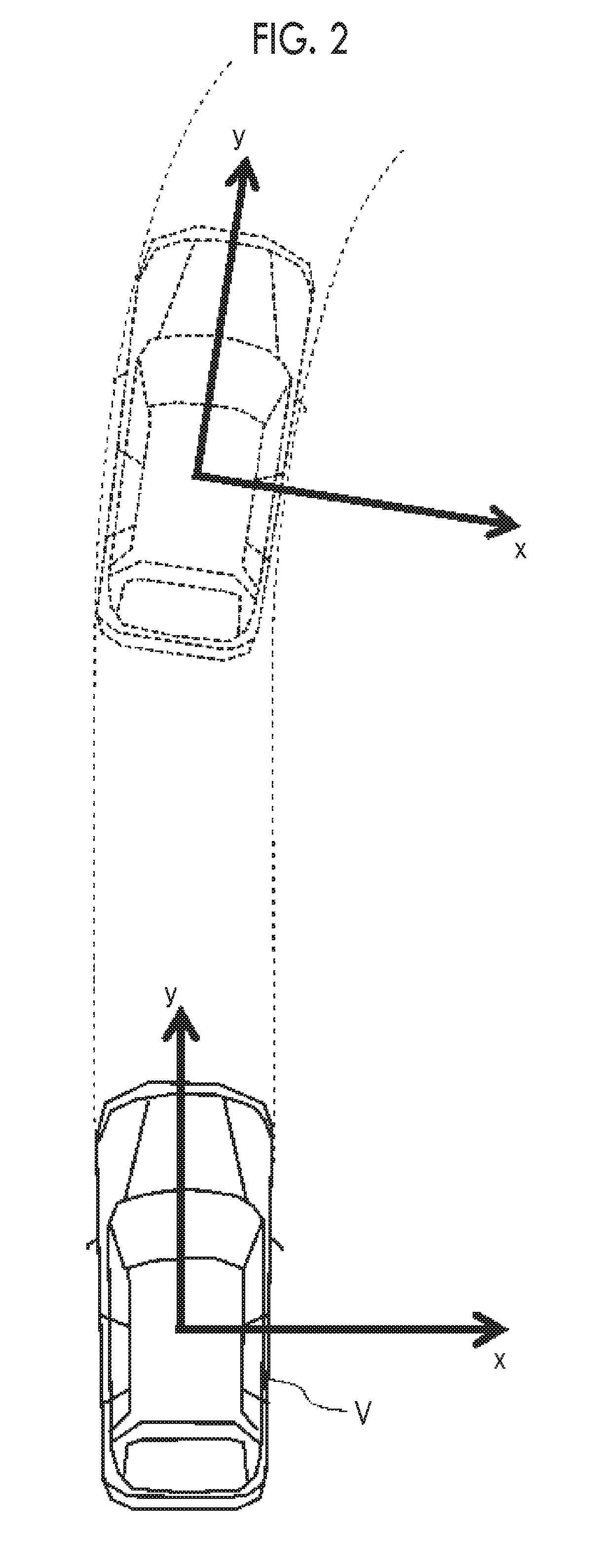
[0040]FIG. 1 is a block diagram showing a configuration of a vehicle V on which a vehicle control device 10 is mounted according to a first embodiment. As shown in FIG. 1, the vehicle control device 10 is mounted on the vehicle V. FIG. 2 is an overhead view for describing an operation of the vehicle V according to the first embodiment.

[0041]The vehicle V includes an external sensor 1, a global positioning system (GPS) receiver 2, an internal sensor 3, a map database 4, a communication unit 5, a navigation system 6, an actuator 7, an informing device 8, and a vehicle control device 10.

[0042]The external sensor 1 is a detector configured to detect environment information (external situation) around the vehicle V. The external sensor 1 includes at least one of a camera or a radar sensor. The camera is an imaging apparatus configured to image a surrounding environment. The camera is provided, for example, on the back side of a windshield of the vehicle V. The camera transmits imaging in...

second embodiment

[0091]A second embodiment will be described. In the description of the embodiment, points different from the first embodiment will be described.

[0092]FIG. 10 is a block diagram showing a configuration of the vehicle V on which a vehicle control device 20 is mounted according to the second embodiment. As shown in FIG. 10, the vehicle control device 20 according to the embodiment differs from the first embodiment in that a human machine interface (HMI) 9, a signal recognition unit 18, and a signal switching time acquisition unit 19 are included.

[0093]The HMI 9 is an interface for inputting and outputting information with the occupant of the vehicle V. Examples of the HMI 9 may include a display panel for displaying image information to the occupant, the speaker for audio output, and an operation button or a touch panel for the occupant to perform an input operation. The HMI 9 displays the image information according to the control signal from the vehicle control device 20 on the displ...


PUM


Abstract

A vehicle control device includes an external situation recognition unit configured to recognize a crossing person who crosses over a path of a vehicle and acquire information on the crossing person and information on an environment where the crossing person crosses, a scheduled departure time deciding unit configured to decide a scheduled departure time of the vehicle based on the information on the crossing person and the environment where the crossing person crosses when the crossing person is recognized by the external situation recognition unit, and an informing controller configured to perform a control to inform an outside of the vehicle of the scheduled departure time. The scheduled departure time deciding unit predicts a crossing completion time at which the crossing person recognized by the external situation recognition unit completes the crossing and decides the scheduled departure time based on the crossing completion time.

Description

INCORPORATION BY REFERENCE[0001]The disclosure of Japanese Patent Application No. 2017-216407 filed on Nov. 9, 2017 including the specification, drawings and abstract is incorporated herein by reference in its entirety.BACKGROUND1. Technical Field[0002]The disclosure relates to a vehicle control device.2. Description of Related Art[0003]In the related art, a person crossing assistance notification system disclosed in Japanese Unexamined Patent Application Publication No. 2013-149296 (JP 2013-149296 A) is known as a system configured to transmit an action schedule of a vehicle to a pedestrian who crosses a road. In the person crossing assistance notification system disclosed in JP 2013-149296 A, the transmission to a person in a vehicle advancing direction is performed by an electric lamp (pedestrian crossing signal display means) mounted on a roof of the vehicle. When the person can safely cross the road while the vehicle is stopped, the person crossing assistance notification syste...

Claims


Application Information

Patent Timeline
Patent Type & Authority Applications(United States)
IPC IPC(8): G08G1/16G08G1/0967G08G1/01
CPCG08G1/166G08G1/096716G08G1/0125G08G1/0137G08G1/096783G05D2201/0213G08G1/005G08G1/096G08G1/09623
Inventor MORIMURA, JUNICHIWATANABE, JUNYAARAKAWA, SEIJI
Owner TOYOTA JIDOSHA KK
Learn More