
Method, assistance system and 3d-printer for computer-aided design of objects for additive manufacturing

a technology of computer-aided design and additive manufacturing, applied in the field of computer-aided design of objects for additive manufacturing, can solve the problems of affecting the optimization of the total mass or the total volume, requiring considerable additional effort, and special to additive manufacturing, and is normally not automatically factored

Inactive Publication Date: 2019-05-09
SIEMENS AG
View PDF2 Cites 3 Cited by
  • Summary
  • Abstract
  • Description
  • Claims
  • Application Information

AI Technical Summary

Benefits of technology

The invention allows for the optimization of objects by automatically adding or removing supporting structures and determining the optimal placement of these structures. This process can lead to a self-supporting design, as there is no need to modify the overall mass or volume of the object. The method also requires less computational resources and allows for interactive changes in design data. The target function can be easily specified and integrated into the optimization process, with the ultimate goal of minimizing overhang angles of object surfaces and edges. Overall, the invention provides a more efficient and effective means of optimizing object designs.

Problems solved by technology

A substantial constraint that needs to be borne in mind with additive manufacturing, however, is that surfaces and edges that overhang to a greater extent normally require a supporting structure during printing, since they would otherwise initially not be connected or would be connected too weakly to other parts of the object to be manufactured in the case of a layered construction.
Supporting structures of this kind need to be added to overhanging surfaces of the object by design prior to printing and need to be removed again after printing, which frequently requires considerable additional effort.
Although known assistance systems for designing objects to be produced frequently assist the designer in making use of an abundance of shapes accessible to additive manufacturing, constraints specific to additive manufacturing, in particular design constraints, are normally not automatically factored in.
Additionally, a total mass or a total volume of the object is not modified by supporting structures, which would hamper optimization of the total mass or of the total volume.

Method used


Image

  • Method, assistance system and 3d-printer for computer-aided design of objects for additive manufacturing
  • Method, assistance system and 3d-printer for computer-aided design of objects for additive manufacturing

Examples


Embodiment Construction

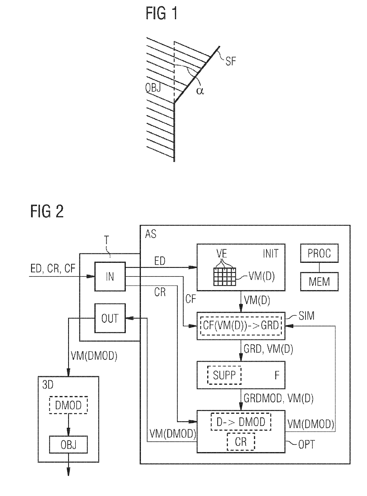
[0023]FIG. 1 illustrates an overhanging lateral face SF of an object OBJ to be additively manufactured, e.g. to be printed by a 3D printer. The overhang angle α in this instance refers to an angle of the object surface SF in relation to the perpendicular. As already mentioned above, if the overhang angle α is too large, supporting structures additionally need to be added before printing and removed again after printing. While an overhang angle α of less than 45° is frequently acceptable, an overhang angle α of more than 45° can require additional supporting structures to be added.

[0024]FIG. 2 shows an assistance system AS for designing an object OBJ to be additively manufactured and a 3D printer 3D for printing the designed object OBJ. The assistance system AS has one or more processors PROC configured to perform all the method steps of the assistance system AS and / or to perform program instructions for performing these method steps. Furthermore, the assistance system AS has one or ...


PUM


Abstract

Design data are input for an object to be additively manufactured and to be optimised in terms of a physical optimisation target is provided. A volumetric model of the object is initialised with a material distribution according to the design data, the volumetric model having a plurality of volume elements. A respective local target property relating to the optimisation target is then determined for volume elements of the volumetric model, based on the material distribution. According to embodiments of the invention, each volume element is checked to determine whether the volume element is supported in terms of additive manufacturing. Based on this, the target property of this volume element is modified in such a way that it approaches the target property if it is supported and / or moves away from the optimisation target if it is not supported.

Description

CROSS-REFERENCE TO RELATED APPLICATIONS[0001]This application claims priority to PCT Application No. PCT / EP2017 / 062732, having a filing date of May 26, 2017, based off of German Application No. 10 2016 210 643.0, having a filing date of Jun. 15, 2016, the entire contents both of which are hereby incorporated by reference.FIELD OF TECHNOLOGY[0002]In contemporary production processes, additive manufacturing is becoming increasingly significant. It permits products having almost arbitrarily complex outlines and topologies to be produced with relatively little effort. Compared with conventional manufacturing methods, only few design constraints need to be observed with additive manufacturing. A substantial constraint that needs to be borne in mind with additive manufacturing, however, is that surfaces and edges that overhang to a greater extent normally require a supporting structure during printing, since they would otherwise initially not be connected or would be connected too weakly ...

Claims


Application Information

Patent Timeline
Patent Type & Authority Applications(United States)
IPC IPC(8): G05B19/4099G06F17/50B33Y50/02
CPCG05B19/4099G06F17/5018B33Y50/02G06F2217/12G05B2219/35134G05B2219/49007B33Y30/00B29C64/386B33Y50/00G06F2111/06G06F30/23G06F30/17G06F2119/18Y02P80/40Y02P90/02G06F2113/10
Inventor WEVER, UTZVITOUX, DAVIDGAVRANOVIC, STEFANHARTMANN, DIRK
Owner SIEMENS AG
Learn More